
 WhatsApp: +86 16626708626
 Email:
  Phone: +86 16626708626
Description
3. Key Technical Specifications
| Parameter | Value |
|---|---|
| Manufacturer | GE Multilin |
| Model | 469-P1-HI-A20-T |
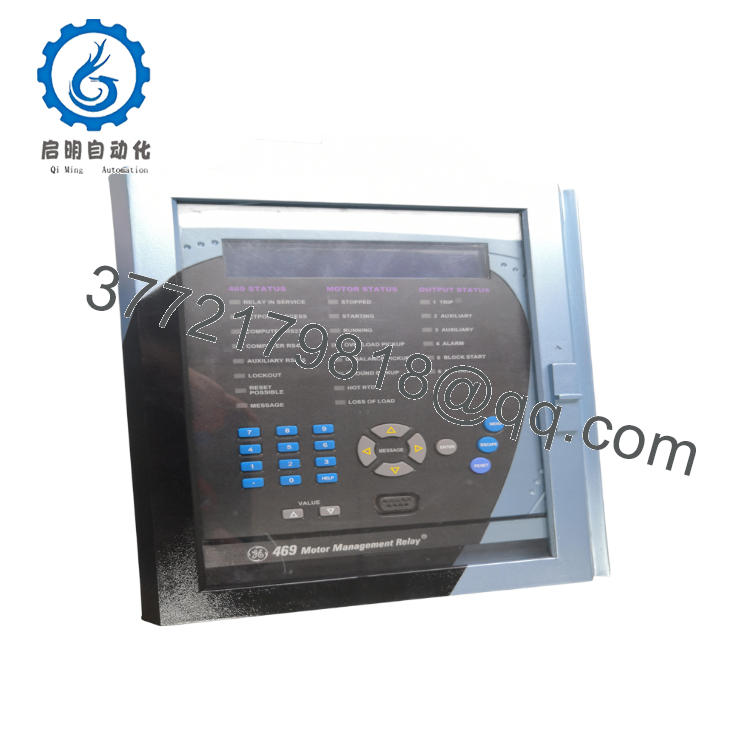
| Product Type | Digital Motor Management Relay |
| Series | Multilin 469 |
| Phase CT Inputs | 1 A secondary |
| Control Power | 90–300 VDC / 70–265 VAC, 48–62 Hz |
| Analog Outputs | Four 4–20 mA outputs |
| Ethernet | Integrated 10Base-T |
| Serial Ports | 1 × RS232, 2 × RS485 |
| Digital Inputs | 9 optically isolated inputs |
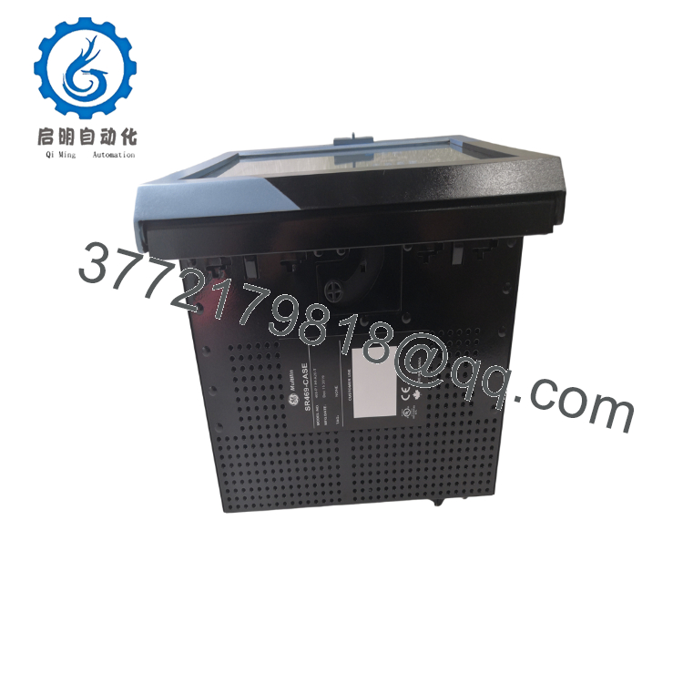
| Construction | Draw-out relay module |
| Display | Enhanced LCD display |
| Configuration Software | GE EnerVista 469 Setup |
| Protection Functions | Thermal overload, locked rotor, stall, phase unbalance, phase loss, ground fault, undercurrent, overcurrent |
| Typical Applications | Medium-voltage motors, pumps, compressors, fans, conveyors, crushers |
The draw-out relay is supplied separately from the SR469 draw-out case.
4. Product Introduction
The GE Multilin 469-P1-HI-A20-T is an intelligent motor management relay developed to protect medium- and large-sized AC motors used in critical industrial processes. It combines protection, metering, diagnostics, event recording, and communications into a single relay, making it suitable for power generation, mining, water treatment, petrochemical, and heavy manufacturing facilities.
This configuration includes 1 A CT inputs, a high-voltage universal control power supply, four 4–20 mA analog outputs, and an enhanced LCD with integrated 10Base-T Ethernet. The Ethernet interface simplifies integration with plant networks and enables faster engineering access through GE EnerVista software.
5. Installation & Configuration Guide
Stage 1 – Pre-Installation Preparation (10 Minutes)
⚠️ Safety First
- Notify operations of the planned outage.
- Perform Lock-Out/Tag-Out (LOTO).
- Isolate both motor and control power supplies.
- Wait at least 5 minutes for internal capacitors to discharge.
- Verify zero voltage using a calibrated multimeter.
Tools Required
- ESD wrist strap
- PH1 screwdriver
- Fluke 115 (or equivalent) multimeter
- Wire identification labels
- Smartphone for wiring photographs
- Laptop with GE EnerVista 469 Setup
Data Backup
- Export relay settings.
- Save event and fault records.
- Record firmware revision.
- Document Ethernet IP address and communication settings.
- Photograph all terminal wiring before removal.
Stage 2 – Removing the Old Relay (5 Minutes)
- Remove the relay front cover if required.
- Label all field wiring.
- Disconnect communication and I/O wiring carefully.
- Release the draw-out locking mechanism.
- Withdraw the relay straight out to protect backplane connectors.
⚠️ Keep the original relay available until commissioning has been completed successfully.
Inspect for:
- Bent connector pins
- Dust contamination
- Loose terminal screws
- Signs of overheating
Stage 3 – Installing the New Relay (10 Minutes)
- Wear an ESD wrist strap.
- Verify the complete model number:
469-P1-HI-A20-T - Insert the relay fully into the draw-out case until the locking mechanism engages.
- Reconnect all field wiring.
- Restore the saved configuration.
- Configure Ethernet communication parameters.
- Verify CT ratio settings before energizing.
Installation Checklist
- ☑ Correct model installed
- ☑ CT ratio verified
- ☑ Wiring secure
- ☑ Ethernet configuration restored
- ☑ Relay fully seated
- ☑ Protective earth verified
Stage 4 – Power-On & Testing (10–15 Minutes)
Before Applying Power
- Check insulation resistance where applicable.
- Verify no short circuits on the control supply.
- Confirm CT secondary circuits remain properly connected.
Commissioning Steps
- Apply control power.
- Observe LED and LCD startup.
- Verify normal RUN status.
- Connect using GE EnerVista through Ethernet or serial communication.
- Confirm firmware version.
- Restore saved settings if required.
- Verify communication with the PLC or SCADA system.
- Perform secondary current injection tests.
- Verify analog outputs and trip contacts.
- Return the motor to service after confirming all protection functions.
⚠️ Troubleshooting
Ethernet communication unavailable
- Verify IP address and subnet mask.
- Check Ethernet switch port status.
- Confirm network cable integrity.
- Verify firewall and engineering workstation settings.
Unexpected motor trips
- Confirm CT polarity.
- Verify motor full-load current settings.
- Review thermal model configuration.
- Check analog input scaling.

- 469-P1-HI-A20-T
- 469-P1-HI-A20-T
6. Frequently Asked Questions (FAQ)
Q1. Can the GE 469-P1-HI-A20-T be hot-swapped?
No. Although the relay uses a draw-out construction, GE does not recommend replacing it while energized. Removing the relay under power interrupts motor protection and may damage the draw-out connector assembly.
Q2. What distinguishes the “T” version from the standard enhanced display?
The T version includes an enhanced LCD display with an integrated 10Base-T Ethernet interface, allowing faster engineering access and easier integration into Ethernet-based plant control systems.
Q3. Does this relay support remote monitoring?
Yes. Through its Ethernet interface and serial communication ports, the relay can communicate with GE EnerVista software and integrate with SCADA or DCS systems using supported industrial communication protocols.
Q4. Is the Multilin 469 still manufactured?
The Multilin 469 is considered a legacy product. Many industrial facilities continue to maintain installed systems using new surplus inventory and professionally tested spare units because of the relay’s long service history.
Q5. Will replacing the relay erase my motor settings?
Not if the configuration is backed up before removal. Always export the complete settings database using GE EnerVista 469 Setup, including protection settings, communication parameters, and event records.
Q6. Why should the firmware version be checked before installation?
Firmware revisions may affect Ethernet communications, event logging, and protection behavior. Installing a relay with a different firmware revision can increase commissioning time if settings require conversion or communication parameters have changed.
Q7. What inspections should be completed before shipment?
A complete quality inspection should include:
- OEM part number and serial number verification
- Visual inspection for corrosion, impact damage, or repair marks
- Power-on self-test
- LCD, keypad, and LED functional verification
- Ethernet and serial communication testing
- Analog output verification (4–20 mA)
- Relay output functional test
- Firmware version documentation
- Final QC approval
- ESD-safe packaging with anti-static protection
For critical shutdown projects, requesting startup photos, a communication test report, and firmware documentation before shipment helps reduce installation risk and shortens commissioning time.



