
 WhatsApp: +86 16626708626
 Email:
  Phone: +86 16626708626
Description
- Key Technical Specifications
- Function: Power connector / PC power board for GE 531X series DC drive assemblies.
- Intended use: 1‑quadrant drives (single-direction motoring) with snubber networks.
- Isolation: Non-common isolation transformer configuration (verify matching transformer topology on your drive).
- Connector type: Board-mounted power connector interfacing drive power stage to control board (verify mating harness and pinout).
- Voltage/current: Matches host 531X drive power ratings — confirm nominal DC bus voltage and current rating on OEM label before installation.
- Mounting: PCB connector card designed to fit 531X chassis slots and mating hardware.
- Environmental: Industrial operating range (confirm exact temperature and humidity limits on unit label).
- Protection: Designed to work with snubbers and related surge suppression components; confirm fuse and breaker coordination.
- Compatibility note: P/N intended for specific 531X module revisions—always match full P/N and suffix to your board and chassis.
- Product Introduction
The GE 531X122PCNAMG1 is a power-connector/PC power board used in GE 531X DC drive families to interface the power electronics and snubber network to the control and harness wiring. It’s specifically arranged for 1‑quadrant applications and a non-common isolation transformer layout, so it’s typically used in single-direction motoring or generator backstop configurations.
Order the exact P/N with suffix and confirm the drive’s DC bus voltage and harness pinout before replacement to avoid incompatible connector or transformer topologies. - Troubleshooting Quick Reference
Symptom Possible Cause Relevance to this Part Quick Check Method Recommendation No DC bus at control board Connector board not seated or input fuse blown ✅ High With power off, inspect mating connector, then measure DC bus continuity through connector pins; check upstream fuses. Reseat connector, replace blown fuses, verify harness continuity before replacing card. Drive trips on over-voltage or surges Snubber or isolation mismatch ✅ High Visually inspect snubber components and measure transient suppression across DC bus with scope during controlled run. Confirm snubber presence and compatibility; replace damaged snubber components; ensure card matches transformer configuration. Intermittent power to drive stage Corroded connector pins or loose retention ✅ High Power down and inspect connector pins for corrosion, bent pins, or loose hardware; wiggle test with power off. Clean/repair connectors; replace card if pins are damaged. Excessive heating at connector High contact resistance or overload ✅ Medium Measure voltage drop across connector under load and check contact temperature with IR thermometer. Tighten/replace connector and verify current rating; upgrade cooling or correct load if needed. Controller reports mismatch P/N or firmware Wrong revision installed ✅ Medium Compare P/N and revision on PCB label to controller compatibility list. Replace with exact P/N/revision; capture label photos and controller logs for support.
Note: Connector-board failures frequently trace back to poor mating, corrosion, or mismatched transformer topology rather than PCB component failure—always photograph labels and connector pinouts before removal.
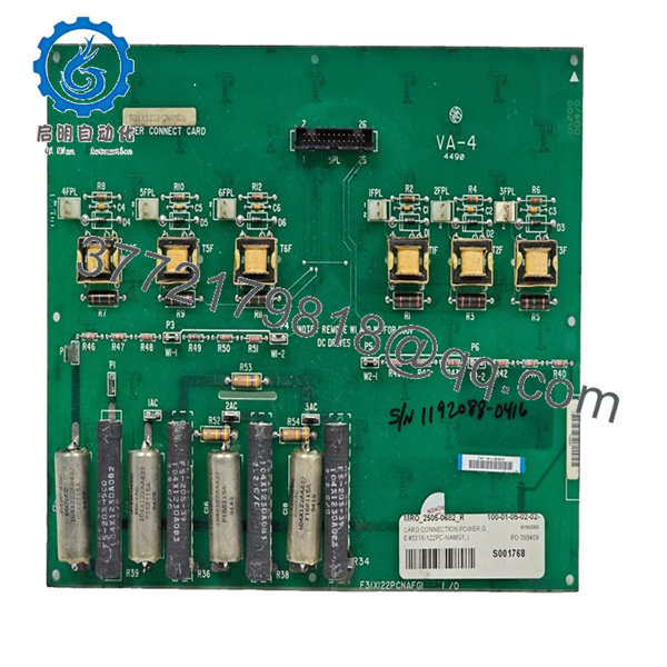
- 531X122PCNAMG1
- 531X122PCNAMG1
- Frequently Asked Questions (FAQ)
Q: Is the 531X122PCNAMG1 hot-swappable?
A: No. Replace this connector card only with rack/chassis power isolated. Hot-swapping power connector cards risks arcing, contact welding, and damage to the drive power stage.
Q: How do I confirm this is the correct replacement for my drive?
A: Match the full P/N including suffix, verify the host 531X drive revision, confirm DC bus voltage and current, and compare connector pinouts and transformer topology before ordering.
Q: What does “1‑quadrant” and “non-common isolation transformer” mean for installation?
A: “1‑quadrant” means the drive is configured for single-direction motoring (no regenerative braking). “Non-common isolation transformer” indicates separate isolated windings rather than a common secondary—mismatching those can change grounding and snubber wiring and will cause faults if replaced incorrectly.
Q: Why might this unit be offered as Refurbished or New Surplus?
A: New Surplus indicates unused OEM inventory sold at discount; refurbished units are repaired and tested. Always confirm declared condition and request the inbound inspection and functional test report.
Q: What tests should I request before shipping?
A: Request source verification, visual inspection, connector/pin audit, power continuity tests, DC bus voltage verification under simulated load, snubber and surge suppression checks, and ESD-safe packaging. Ask for photos and measured voltage logs.
Q: What warranty and lead times apply?
A: Lead time and warranty vary by condition—New Surplus often ships same-week with a 1-year limited warranty; refurbished units usually ship in 3–7 business days with a 90-day functional warranty. Confirm at order.
Critical pitfall reminders:
- Photograph the board label and mating harness pinout before removal.
- Power down the chassis and use ESD precautions when handling the board.
- Verify snubber presence and transformer topology to prevent wiring mismatches.
- Measure DC bus voltage and connector continuity before assuming PCB failure.


