
 WhatsApp: +86 16626708626
 Email:
  Phone: +86 16626708626
Description
3. Key Technical Specifications
| Parameter | Value |
|---|---|
| Manufacturer | GE Fanuc |
| Model | 705-1512-01 |
| Product Type | Analog Output Module |
| PLC Family | Series 90-30 (reported) |
| Analog Outputs | 4 Channels |
| Output Signal | 0–10 VDC or 4–20 mA (configuration dependent) |
| Resolution | 12-bit |
| Accuracy | ±0.1% Full Scale |
| Update Rate | Approximately 2.5 ms per channel |
| Power Consumption | Approximately 2.5 W |
| Operating Temperature | –20 °C to +60 °C |
| Storage Temperature | –40 °C to +80 °C |
| Installation | PLC Rack Module |
| Typical Applications | Process control, valve positioning, variable-speed drives, industrial automation |
Because GE has not published a readily available datasheet for this specific catalog number, electrical specifications should be verified before installation.
4. Product Introduction
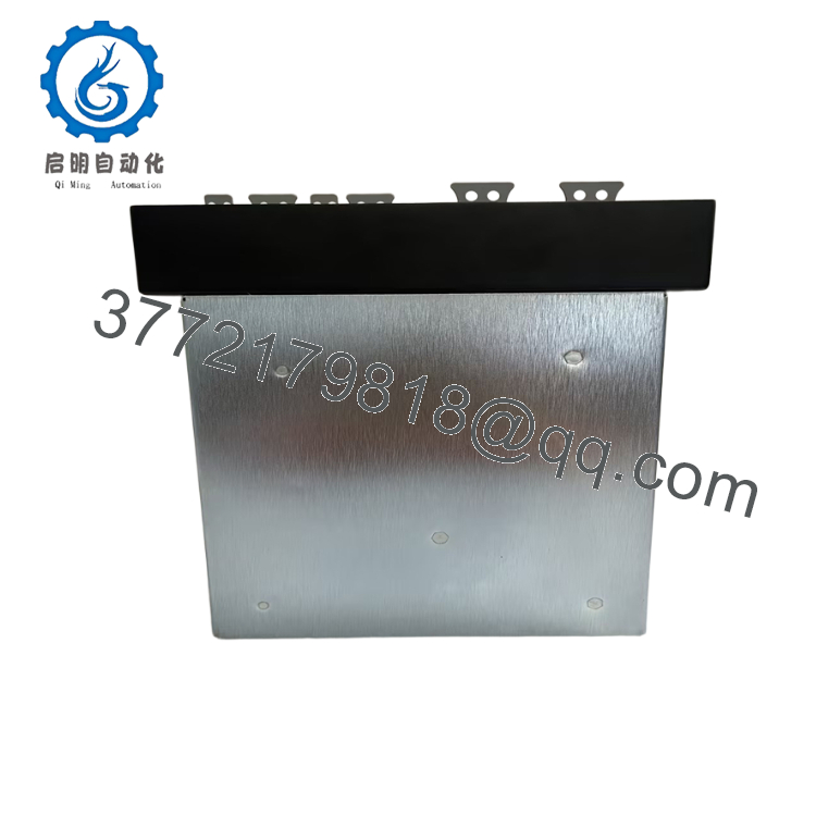
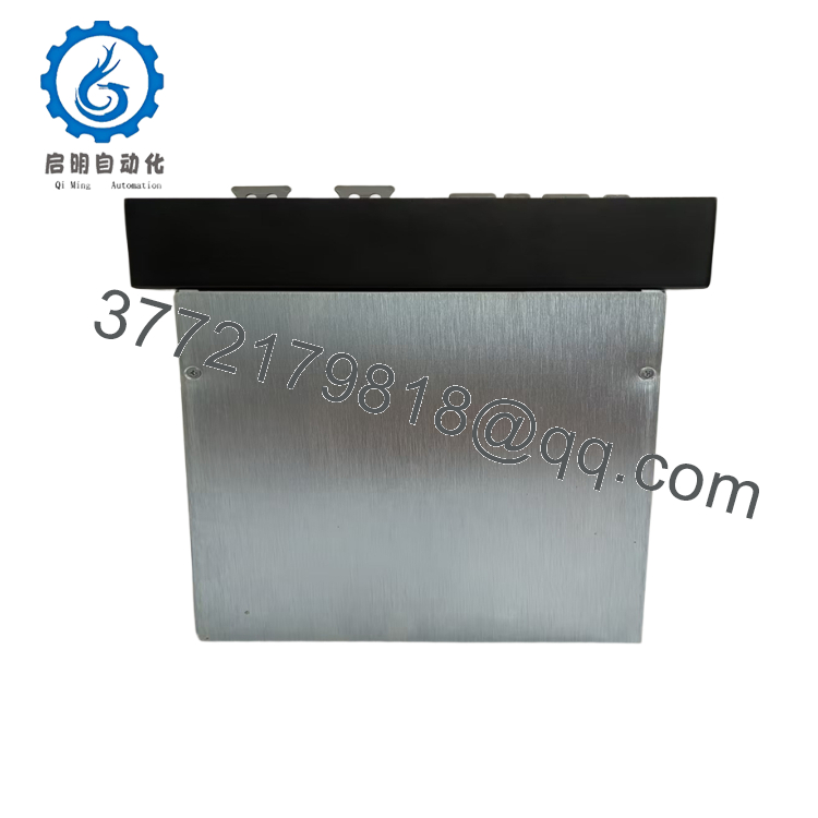
The GE 705-1512-01 is a legacy analog output module designed for GE Fanuc PLC systems, providing analog control signals for field devices such as control valves, variable-frequency drives, dampers, and process actuators. It converts PLC output values into standard industrial voltage or current signals for process automation applications.
Its 12-bit resolution and support for common industrial analog output ranges make it suitable for manufacturing, water treatment, utilities, and process industries. Since this module belongs to a legacy automation platform, replacement units should be matched carefully for hardware revision, rack compatibility, and wiring configuration before commissioning.

- 705-1512-01
- 705-1512-01
5. Installation & Configuration Guide
Stage 1 – Pre-Installation Preparation (10 Minutes)
⚠️ Safety First
- Notify operations of the planned shutdown.
- Perform Lock-Out/Tag-Out (LOTO).
- Remove PLC rack power.
- Wait at least 5 minutes before removing modules.
- Verify zero voltage using a calibrated multimeter.
Tools Required
- ESD wrist strap
- Phillips screwdriver
- Fluke 115 (or equivalent)
- Wire identification labels
- Smartphone for wiring photographs
- Programming workstation
Data Backup
- Back up the PLC application.
- Record analog scaling parameters.
- Photograph wiring and terminal assignments.
- Record module slot location.
- Document output channel calibration values.
Stage 2 – Removing the Existing Module (5 Minutes)
- Label every field cable.
- Disconnect terminal blocks carefully.
- Unlock the module retaining mechanism.
- Remove the module straight out without twisting.
- Inspect the backplane connector.
⚠️ Retain the original module until the replacement has passed commissioning.
Inspect for:
- Bent connector pins
- Corrosion
- Dust buildup
- Loose terminals
Stage 3 – Installing the New Module (10 Minutes)
- Wear an ESD wrist strap.
- Verify the complete part number:
705-1512-01 - Confirm rack compatibility.
- Insert the module evenly until fully seated.
- Secure the retaining mechanism.
- Reconnect all field wiring.
- Restore analog output scaling and configuration.
Installation Checklist
- ☑ Correct model verified
- ☑ Module fully seated
- ☑ Wiring confirmed
- ☑ Output scaling restored
- ☑ Ground connection verified
Stage 4 – Power-On & Functional Testing (10–15 Minutes)
Before Applying Power
- Verify supply voltage.
- Inspect wiring for shorts.
- Confirm field devices are isolated if required.
Commissioning Steps
- Energize the PLC rack.
- Verify module status indicators.
- Confirm PLC recognizes the module.
- Download the PLC application if necessary.
- Test each analog output individually.
- Verify output values with a calibrated meter.
- Confirm proper operation of connected field devices.
⚠️ Troubleshooting
No analog output
- Verify PLC configuration.
- Confirm channel scaling.
- Check external power requirements.
- Inspect field wiring continuity.
Output signal inaccurate
- Verify engineering units.
- Check output range configuration (0–10 V vs. 4–20 mA).
- Recalibrate if required.
6. Frequently Asked Questions (FAQ)
Q1. Is the GE 705-1512-01 still manufactured?
No. This is a legacy GE Fanuc automation component. Most available inventory consists of new surplus, refurbished, or professionally tested units.
Q2. Can this module be hot-swapped?
No. Series 90 PLC analog modules are generally not intended for hot swapping unless the specific system architecture explicitly supports it. Removing the module under power can interrupt process control and may damage the backplane.
Q3. What should I verify before ordering?
Confirm:
- Complete part number (705-1512-01)
- PLC platform (Series 90-30 or installed system)
- Rack compatibility
- Output type (voltage or current)
- Wiring terminal configuration
- Hardware revision
Because publicly available information is inconsistent for this catalog number, checking the original module label is strongly recommended.
Q4. Will replacing the module affect the PLC program?
Normally, no. The application program is stored in the PLC CPU rather than the I/O module. However, analog scaling, channel assignments, and hardware configuration should be verified after installation.
Q5. What is the most common installation mistake?
The most frequent issue is configuring the wrong output mode. Installing a module configured for 0–10 V when the field device expects 4–20 mA can result in incorrect actuator movement or unstable process control. Always verify both PLC configuration and field device requirements before energizing.
Q6. Why are new surplus modules still available?
Many legacy GE Fanuc modules come from plant modernization projects, distributor excess inventory, or unused maintenance stock. These genuine OEM parts remain valuable because many facilities continue to operate legacy PLC systems.
Q7. What quality inspections should be completed before shipment?
A comprehensive inspection should include:
- OEM part number and serial number verification
- Visual inspection for corrosion, damaged traces, and connector wear
- Power-on functional testing in a compatible GE Fanuc PLC rack
- Analog output verification on all channels
- Electrical isolation and continuity checks
- Final QC approval
- ESD-safe packaging with anti-static protection
For critical maintenance shutdowns, requesting analog output calibration results and a functional test report before shipment can help reduce commissioning time and minimize installation risk.



