
 WhatsApp: +86 16626708626
 Email:
  Phone: +86 16626708626
Description
3. Order Code Nomenclature Breakdown
Using the official GE Multilin SR 750 series ordering system, this exact part number configures the following hardware and software parameters:
| Code Segment | Parameter | Selected Option Details |
| 750 | Base Relay Model | Multilin 750 Feeder Management Relay |
| P5 | Phase Current Inputs | 5 Amp secondary Phase CT inputs |
| G5 | Ground Current Inputs | 5 Amp secondary Zero Sequence (Ground) CT inputs |
| S5 | Sensitive Ground | 5 Amp secondary Sensitive Ground CT input |
| HI | Control Voltage Supply | Wide-Range: 88–300 VDC / 70–265 VAC (48–62 Hz) |
| A20 | Analog Outputs | Eight active 4–20 mA analog outputs (internally sourced) |
| R | Breaker Status LED | Red Breaker Closed LED (Default standard configuration) |
| T | Communications | Enhanced front display screen and rear 10BaseT Ethernet port |
4. Key Technical Specifications
| Parameter | Value |
| Phase / Ground Current CTs | 5A secondary rating (burden < 0.2 VA at 5A) |
| Sensitive Ground CT | 5A secondary rating (range typically 0.005 to 5.000 A) |
| Voltage VT Inputs | 3-phase Wye/Delta connection capability; range 50 to 240 VAC continuous |
| Auxiliary Operating Power (HI) | 88–300 VDC (typical 35W draw) / 70–265 VAC (typical 35VA @ 48–62 Hz) |
| Analog Outputs (A20) | 8 channels of 4–20 mA loop outputs (Max. load 600 \Omega) |
| Trip Relay Contacts | Rated for 250 VAC @ 10A Continuous |
| Front Serial Interface | RS-232 port for direct laptop setup via EnerVista |
| Rear Communication Interfaces | 2 x RS-485 serial loops (Modbus RTU) & 1 x 10BaseT RJ-45 Ethernet port |
| Physical Construction | Compact draw-out chassis with integrated cover seal handle |
| Environmental Parameters | Operating Temperature: -40°C to +60°C (-40°F to +140°F) |
5. Product Introduction & Application Strategy
The GE Multilin SR750-P5-G5-S5-HI-A20-R-T is a highly versatile, digital feeder protection relay developed for primary control and management of industrial substation distribution feeders. Armed with an intensive library of protection elements (including directional and non-directional time overcurrent, instantaneous overcurrent, under/overvoltage, and under/overfrequency), this unit manages safety envelopes across utility networks. The inclusion of eight 4–20 mA analog outputs and dual 5A ground loops (standard ground and ultra-sensitive ground) enables it to handle precise telemetry feedback and sensitive earth fault protections for high-resistance grounded systems.
From a procurement perspective, the SR750-P5-G5-S5-HI-A20-R-T is a high-impact infrastructure asset. When feeder relays fail, downstream distribution grids must be isolated, leaving whole production blocks or plant modules in total blackout.
Sourcing this module as a certified New Surplus unit protects your distribution systems from the failure risks common in third-party repaired boards. Refurbished relays often have worn out capacitors, drifted internal analog references, or compromised draw-out connection pins that risk intermittent signals. Storing a factory-sealed, zero-hour surplus SR750 on your shelf provides immediate recovery, avoiding the long lead times of modern retrofit migrations.
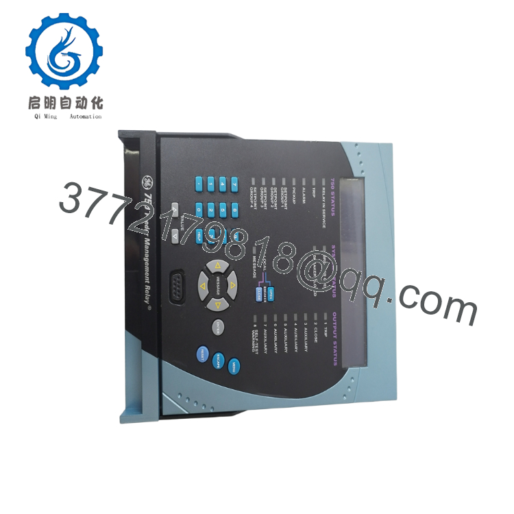
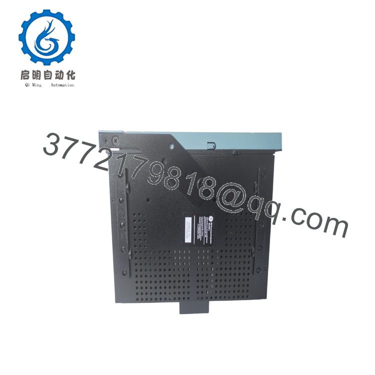
- 750-P5-G5-S5-HI-A20-R-T
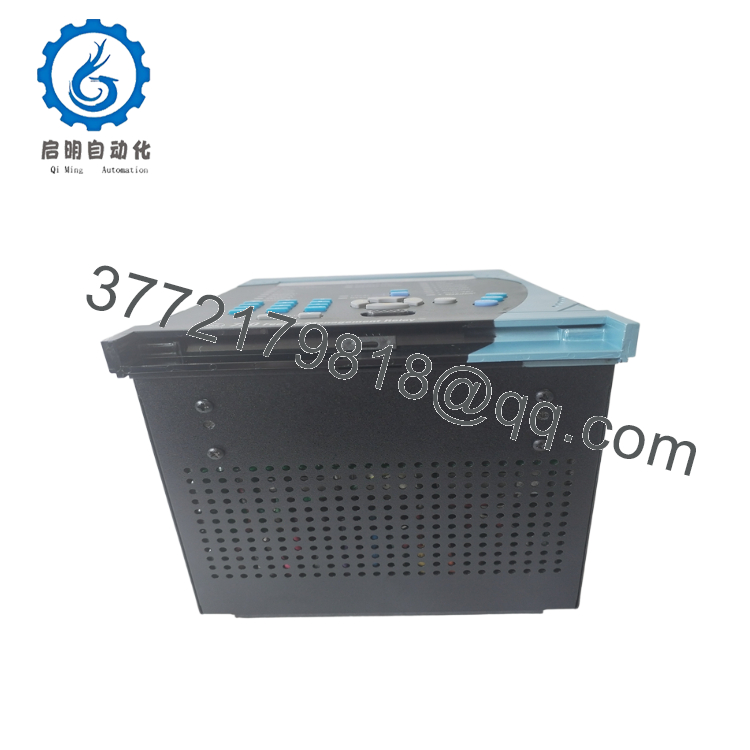
- 750-P5-G5-S5-HI-A20-R-T

- 750-P5-G5-S5-HI-A20-R-T
6. Installation & Network Integration Guide
Stage 1: Pre-Installation Prep
Verify that the primary distribution breaker feeding the target circuit is completely locked out and tagged out (LOTO). Verify that all active current transformer (CT) secondaries are shorted out at the test switch block to prevent dangerous high-voltage open circuits. Put on a grounded ESD wrist strap before sliding the relay card out of its anti-static protective packaging.
Stage 2: Mechanical Insertion
The SR750 utilizes a draw-out casing mechanism. To install the unit:
- Lift the integrated pull-out handle on the front panel and pull it fully outward.
- Align the replacement chassis with the card guide tracks of the pre-mounted outer panel case.
- Slide the relay chassis smoothly into the guides until it is almost flush.
- Press the handle downward until it clicks and locks into place, engaging the rear connection fingers with the backplane block.
⚠️ ETHERNET REAR PORT EXPOSURE: The “T” option equips the rear of this relay with a physical RJ-45 10BaseT Ethernet port. If you are swapping this unit into a legacy panel case that previously housed a non-Ethernet unit (such as an older standard SR750-P5-G5-S5-HI-A20-R), check the backplate of the existing metal enclosure. You may need to remove a rear breakout plate or install an Ethernet-compatible case to ensure the RJ-45 cable port is exposed and accessible.
Stage 3: Wiring Configuration
Terminate all field connections at the rear of the case:
- Current Inputs: Land the Phase CTs on the P5 terminals, Ground CTs on the G5 terminals, and the Sensitive Ground loop on the S5 terminals.
- Control Voltage: Wire the 110/220 VDC or VAC operating power directly to the designated “HI” input terminals.
- Networking: Connect your Cat5e patch cable directly to the rear RJ-45 port for connection to your Ethernet network switches.
Stage 4: Configuration Download
- Energize the local DC/AC control power supply. The unit’s front LCD screen will boot and initialize the English interface.
- Connect your workstation to the front RS-232 port or via Ethernet Modbus TCP.
- Open the EnerVista 750/760 Setup program.
- Upload your facility’s specific setting file (.750 format). Verify CT/VT ratios, overcurrent curve characteristics, and the IP network settings.
- Manually press the front “Reset” button to clear any startup target codes. Confirm the “Ready” status LED displays a solid green.
7. Frequently Asked Questions (FAQ)
What is the “S5” (Sensitive Ground) current input used for?
The S5 input is designed to monitor low-level leakage currents down to the milliamp range. This is particularly vital in high-impedance grounded distribution systems, where a single phase-to-ground fault produces very little fault current. The sensitive ground input allows the SR750 to detect these low-current faults early, protecting equipment and personnel before the fault can develop into a major phase-to-phase short.
Is this GE Multilin 750 relay a refurbished or salvaged component?
No. This is a Brand New Surplus unit. It has not been used, has not been recovered from a decommissioned panel, and has not undergone third-party electronic repairs. The relay is delivered inside its original protective packaging, featuring clean contact tracks, a scratch-free front display, and untouched internal memory registers.
Can I hot-swap this relay while the feeder circuit is active?
While the draw-out case is mechanically designed to allow quick removal of the active module, you should never extract the chassis while current is flowing through the primary feeder. Pulling the relay while active can open-circuit your CT lines, generating extremely high voltages that can damage the backplane connectors and pose a severe safety hazard to technicians. Always isolate the circuit and short the secondary CT loops at the test blocks before pulling the relay.
What warranty terms cover this legacy protective relay?
Every New Surplus SR750-P5-G5-S5-HI-A20-R-T relay comes with our comprehensive 1-year operational warranty from your date of purchase. If any hardware or component defect occurs during this period under normal operating parameters, we will facilitate an immediate replacement or repair.



