
 WhatsApp: +86 16626708626
 Email:
  Phone: +86 16626708626
Description
3. Key Technical Specifications
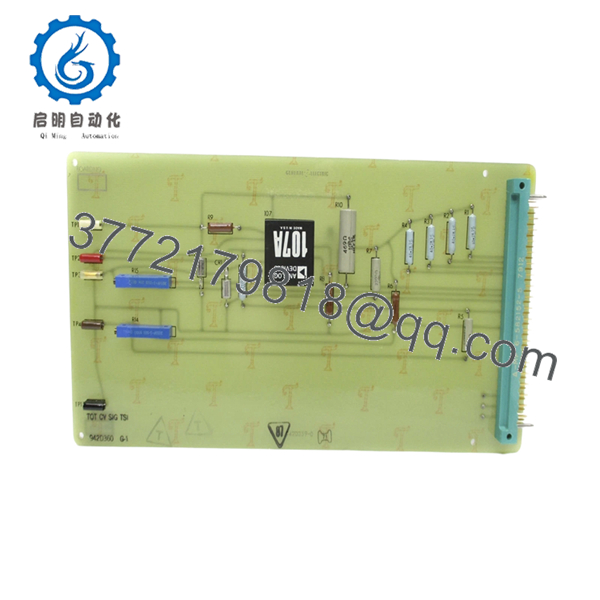
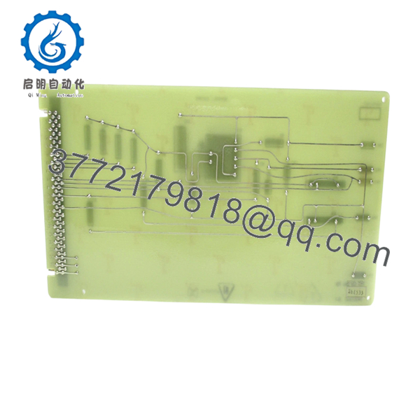
- Product Type: Printed Circuit Board (PCB)
- Function Category: Control / signal conditioning board
- System Integration: Installed in GE control cabinets or drive systems
- Processor / Logic: Discrete logic + analog circuitry (no modern CPU architecture)
- Power Supply: Backplane or system-fed DC supply (varies by system)
- Connectors: Edge connector interface to rack/backplane
- Application: Turbine control / drive systems / industrial panels
- Operating Temperature: Typically 0 to 60°C (system dependent)
- Mounting: Slot-in card (rack or enclosure mounted)
- Weight: ~0.5–1.0 kg (typical PCB assembly range)
4. Product Introduction
The GE 942D360G-1 is a legacy industrial PCB circuit board used in older GE control systems, typically within turbine, drive, or process control cabinets. It performs signal conditioning and control logic functions at the hardware level rather than through a programmable CPU.
In real installations, these boards show up in pre-Mark V or early drive control architectures. Replacement demand is driven by aging infrastructure where full system migration is not justified. Engineers usually source identical boards to avoid redesigning control loops or revalidating the system.
- 942D360G-1
5. Installation & Configuration Guide
Stage 1: Pre-Installation Preparation (Estimated Time: 15 min)
- ⚠️ Safety First: Shut down system, isolate power, lock out/tag out, wait minimum 5 minutes.
- Tools Required: ESD wrist strap, insulated screwdriver, multimeter, labels, smartphone.
- Data Backup:
- Photograph wiring harnesses and connector orientation.
- Document board slot position and adjacent modules.
- Record any adjustable components (potentiometers, jumpers).
Stage 2: Removing the Old Module (Estimated Time: 10 min)
- Open control cabinet and locate the board.
- Label all connectors before removal.
- Disconnect cables carefully—older headers can be brittle.
- Release retaining clips and pull board straight out.
- Inspect for burnt components or backplane damage.
- ⚠️ Note: Keep the original board for reference, especially for jumper or trim settings.
Stage 3: Installing the New Module (Estimated Time: 10–15 min)
- Apply ESD protection before handling.
- Verify exact model: 942D360G-1 (no suffix mismatch).
- Replicate all jumper settings and adjustable trims.
- Insert board firmly into slot—ensure proper alignment.
- Reconnect all cables securely.
- Self-Checklist:
- Jumpers and trims match
- Connectors seated correctly
- Board fully inserted
Stage 4: Power-On & Testing (Estimated Time: 15–20 min)
- Pre-Power Check:
- Verify no short circuits using multimeter.
- Inspect connectors and cable strain.
- Power-On Steps:
- Energize control cabinet.
- Monitor system startup behavior.
- Validate signal paths (analog/digital).
- Confirm system returns to normal operation.
- ⚠️ Troubleshooting Note:
- No response → connector misalignment or backplane issue
- Erratic signals → incorrect jumper or trim settings
6. Frequently Asked Questions (FAQ)
Q1: What exactly does this board do?
It’s not a smart module. This is hardware-level control—signal conditioning, amplification, or logic gating depending on the system. You won’t find firmware or software diagnostics like modern PLC modules.
Q2: Is this board still manufactured by GE?
No. This is long obsolete. Availability is limited to surplus or refurbished stock.
Q3: Can I replace it with a newer GE module?
No direct replacement exists. You’re looking at a system-level upgrade if you want to move away from this hardware.
Q4: Why is replacement tricky compared to PLC modules?
Because configuration isn’t digital—it’s physical. Jumpers, resistors, and trim pots define behavior.
I’ve seen engineers swap boards and forget a trim setting—system drifted for hours before anyone caught it.
Q5: Can I hot-swap this board?
No. These legacy boards are not designed for live insertion. You risk damaging both the board and the backplane.
Q6: What typically fails on this type of board?
From field experience:
- Electrolytic capacitors drying out
- Solder joint fatigue
- Analog drift in signal conditioning circuits
Q7: What’s the biggest installation risk?
❗ Misalignment during insertion.
These older connectors don’t forgive mistakes. I’ve seen one bent pin take down an entire control rack.


