
 WhatsApp: +86 16626708626
 Email:
  Phone: +86 16626708626
Description
3. Key Technical Specifications
- Application: GE turbine or industrial control systems (legacy platforms)
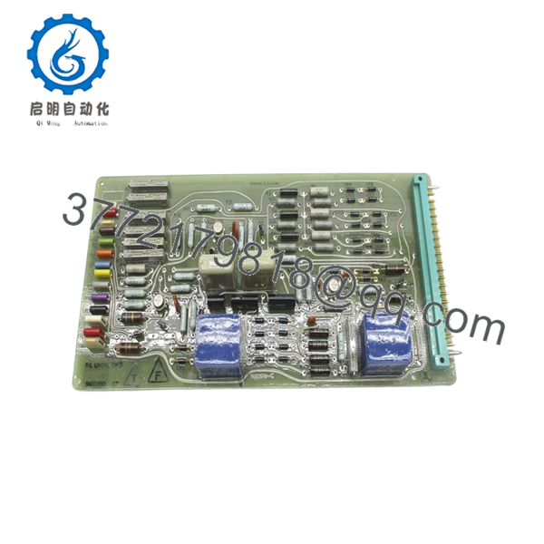
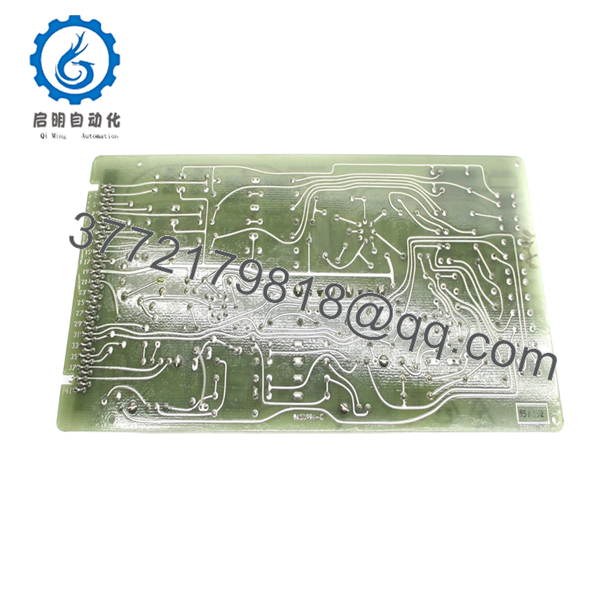
- Board Type: Control and interface PCB
- Functionality: Signal conditioning, control logic distribution
- Input Signals: Analog and discrete inputs (system dependent)
- Output Signals: Control outputs to actuators or logic modules
- Interface: Proprietary GE connectors/backplane
- Power Supply: Backplane-powered (typical internal rails 5 V / 24 V)
- Operating Temperature: 0°C to +60°C
- Construction: Industrial multi-layer PCB, mixed SMD/through-hole
- Mounting: Rack-mounted or panel-installed (application dependent)
- Estimated Dimensions: Standard GE board format (~12 × 8 in class)
- Weight: ~0.5–1.2 kg
4. Product Introduction
The GE 948D895G7 is an industrial control PCB used in GE turbine or auxiliary control systems, responsible for signal processing and interfacing between field inputs and system-level control logic. It operates within GE’s proprietary rack or panel-based architectures.
In practice, this type of board shows up in legacy installations where full system migration (e.g., to Mark VIe or third-party DCS) is not economically justified. Engineers typically source exact-match replacements to maintain system stability and avoid revalidation of control loops.
- 948D895G7
- 948D895G7
5. Installation & Configuration Guide
Stage 1: Pre-Installation Preparation (Estimated Time: 10–15 min)
- ⚠️ Safety First:
Bring the system to a safe shutdown state, isolate all power, apply lockout/tagout, and wait at least 5 minutes for discharge. - Tools Required:
ESD wrist strap, PH1 screwdriver, Fluke 115 multimeter, wire labels, smartphone. - Data Backup:
- Photograph board position and all connectors
- Record cable routing and terminal layout
- Capture current system alarms or abnormal signals
Stage 2: Removing the Old Module (Estimated Time: 5–10 min)
- Open cabinet and locate the 948D895G7 board.
- Label every connector before removal.
- Disconnect wiring carefully — avoid stressing connectors.
- Remove mounting hardware or release card guides.
- Pull the board straight out to protect connector pins.
- Inspect mating connectors for oxidation or damage.
- ⚠️ Note: Keep the original board on-site. It’s your baseline for troubleshooting.
Stage 3: Installing the New Module (Estimated Time: 5–10 min)
- Apply ESD protection before handling.
- Verify exact model: 948D895G7 (no revision mismatch).
- Configuration Clone (Critical):
- Check for jumpers, resistor packs, or hardware options
- Replicate any non-default configurations
- Insert into the correct slot or mounting location.
- Ensure full seating — no partial insertion.
- Reconnect all wiring exactly as labeled.
- Self-Checklist:
[ ] Model verified
[ ] Wiring matched
[ ] Fully seated
[ ] No bent pins
Stage 4: Power-On & Testing (Estimated Time: 10–15 min)
- Pre-Power Check:
Measure supply rails for shorts before energizing. - Power-On Steps:
- Energize control system only (keep process offline).
- Observe system indicators and alarms.
- Verify communication with related modules.
- Check signal values via HMI or diagnostics.
- Perform controlled functional test before full operation.
- ⚠️ Troubleshooting Note:
- No response → check connector seating and wiring order
- Intermittent signals → inspect grounding/shielding
- Immediate fault → suspect wrong revision or configuration mismatch
6. Frequently Asked Questions (FAQ)
Q1: Can this board be hot-swapped?
No. These GE legacy control boards are not designed for hot-swapping. You risk damaging the backplane or introducing transient faults. Always power down.
Q2: Is GE 948D895G7 obsolete?
Yes. This is a legacy industrial control PCB. OEM production has stopped; availability depends on surplus inventory.
Q3: Are similar GE boards interchangeable?
Not reliably. GE reused layouts across families, but signal paths and component values differ. I’ve seen “similar-looking” boards cause unstable control loops.
Q4: Does this board store control logic?
Typically no. Logic resides in the main controller. This board handles signal interfacing, so after replacement, verify scaling and signal integrity.
Q5: Why do these boards fail after long service?
Common causes:
- Capacitor aging (10–20 year lifecycle)
- Thermal cycling inside cabinets
- Connector oxidation
Q6: Why is there limited technical documentation available?
GE legacy boards often had documentation restricted to OEM service manuals. In many cases, only system-level diagrams are available, not detailed PCB schematics.
Q7: What’s the most common replacement mistake?
❗ Misidentifying the board revision or wiring connectors.
I’ve seen outages extended by hours because a connector was shifted one position. Take photos before removal—every time.


