
 WhatsApp: +86 16626708626
 Email:
  Phone: +86 16626708626
Description
3. Key Technical Specifications
| Parameter | Value |
|---|---|
| Manufacturer | GE (Legacy ALSTOM / GE Energy) |
| Model | ADU232.1 029.223006 |
| Product Type | Communication Interface Module |
| Module Family | ADU232 |
| Primary Function | Serial communication interface |
| Communication Port | RS-232 |
| Mounting | Rack-mounted PCB module |
| Diagnostics | LED status indicators (configuration dependent) |
| Firmware | Embedded firmware (revision dependent) |
| Cooling | Passive cabinet cooling |
| Installation | Control system rack |
| Typical Applications | Turbine control, power generation, DCS communication gateways |
| Condition | New Original / New Surplus |
Exact electrical ratings and communication parameters should be verified against the installed equipment because publicly available OEM specifications for this specific part number are limited.
4. Product Introduction
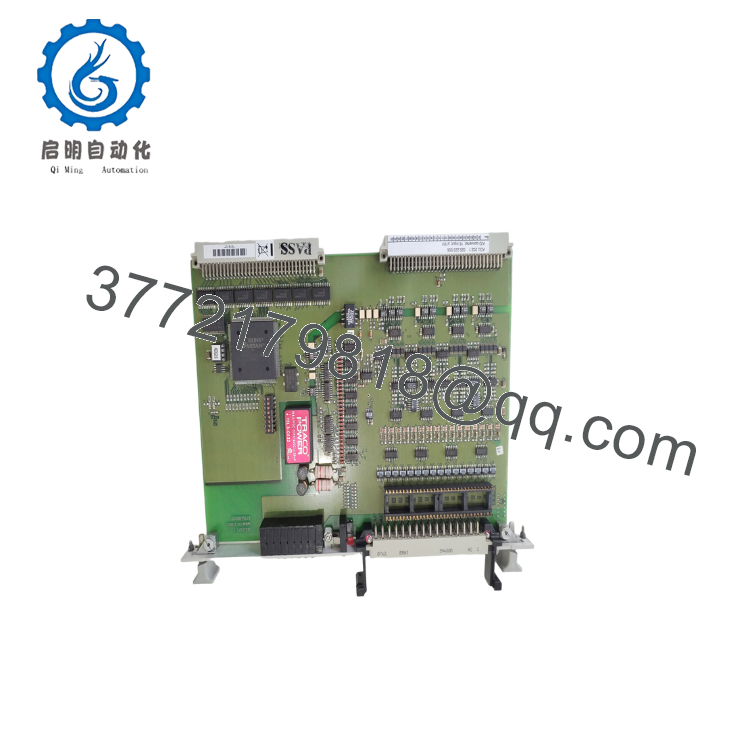
The GE ADU232.1 029.223006 is a legacy communication interface module used in GE Energy and former ALSTOM industrial control systems. Its primary function is to provide serial communications between the controller and external engineering workstations, HMIs, or supervisory control systems through an RS-232 interface.
The module is commonly found in power generation and industrial automation applications where dependable serial communications remain part of the existing control architecture. Because this platform has been discontinued for many years, replacement modules should be matched carefully for hardware revision and firmware compatibility before installation.

- ADU232.1 029.223006
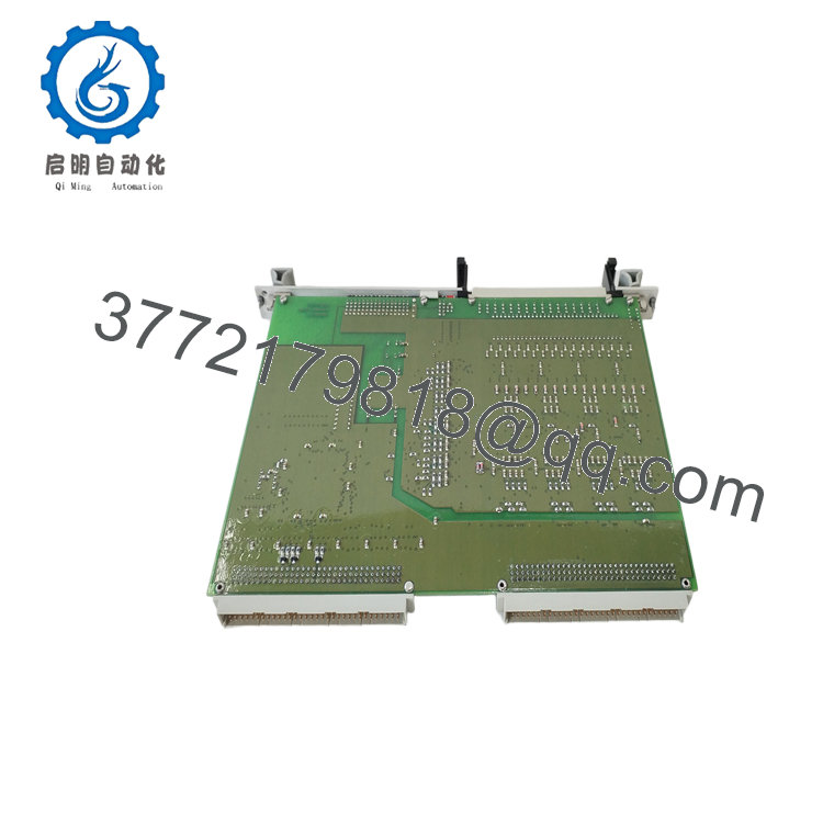
- ADU232.1 029.223006
5. Installation & Configuration Guide
Stage 1 – Pre-Installation Preparation (10 Minutes)
⚠️ Safety First
- Notify operations of the planned maintenance.
- Perform Lock-Out/Tag-Out (LOTO).
- Isolate all control power supplies.
- Wait at least 5 minutes for internal capacitors to discharge.
- Verify zero voltage using a calibrated multimeter.
Tools Required
- ESD wrist strap
- Phillips screwdriver
- Fluke 115 or equivalent multimeter
- Cable identification labels
- Smartphone for wiring documentation
- Engineering workstation
Data Backup
- Record firmware revision.
- Document communication parameters (baud rate, parity, node address).
- Photograph connector locations.
- Label every communication cable.
- Record rack slot position.
Stage 2 – Removing the Existing Module (5 Minutes)
- Open the control cabinet.
- Confirm control power is OFF.
- Disconnect all serial communication cables.
- Release retaining hardware.
- Remove the module straight out to avoid connector damage.
⚠️ Keep the original module until the replacement has completed commissioning successfully.
Inspect:
- Edge connectors
- Rack backplane
- Dust contamination
- Bent connector pins
Stage 3 – Installing the New Module (10 Minutes)
- Wear an ESD wrist strap.
- Verify the complete part number:
ADU232.1 029.223006 - Confirm hardware and firmware compatibility.
- Insert the module fully into the rack.
- Secure retaining hardware.
- Reconnect communication cables.
- Restore the original communication settings.
Installation Checklist
- ☑ Correct part number
- ☑ Firmware verified
- ☑ Rack slot confirmed
- ☑ Communication cables secured
- ☑ Ground connection verified
Stage 4 – Power-On & Commissioning (10–15 Minutes)
Before Applying Power
- Inspect all connectors.
- Verify supply voltage.
- Check for loose wiring.
Commissioning Steps
- Apply control power.
- Observe LED status indicators.
- Confirm normal startup.
- Connect from the engineering workstation.
- Verify RS-232 communication.
- Confirm data exchange with the host controller.
- Review diagnostic logs.
- Return the system to service after successful communication testing.
⚠️ Troubleshooting
No serial communication
- Verify baud rate, parity, and stop-bit settings.
- Check RS-232 cable pinout.
- Confirm COM port configuration.
- Inspect connector seating.
Module not detected
- Verify rack position.
- Confirm firmware compatibility.
- Check backplane power.
- Inspect edge connectors for contamination.
6. Frequently Asked Questions (FAQ)
Q1. Is the GE ADU232.1 029.223006 still manufactured?
No. This is a legacy communication module that is no longer in production. Most available units are sourced from new surplus inventory, plant spare-part stock, or professionally refurbished equipment.
Q2. Can this module be hot-swapped?
No. Legacy GE and ALSTOM communication modules are generally not designed for hot swapping. Removing the module while energized can interrupt controller communications and may damage the backplane.
Q3. What should I verify before ordering?
Confirm the following:
- Complete model number (ADU232.1 029.223006)
- Hardware revision
- Firmware version
- Rack location
- Communication protocol
- RS-232 cable configuration
Matching only the base model number may not guarantee compatibility in legacy control systems.
Q4. Will replacing the module affect the controller application?
Normally, no. The application software resides in the main controller. However, communication settings and firmware compatibility should be verified after installation to ensure reliable data exchange.
Q5. What is the most common installation mistake?
The most common issue is overlooking the serial communication parameters. A replacement module configured with different baud rate, parity, or addressing can appear to be faulty even though the hardware is operating correctly. Always record these settings before removing the original module.
Q6. Why are new surplus units still available?
Many legacy GE and ALSTOM spare parts originate from plant upgrades, canceled modernization projects, or distributor inventory. These genuine OEM components continue to support facilities that maintain long-service-life control systems.
Q7. What quality inspections should be completed before shipment?
A complete inspection should include:
- OEM part number and serial number verification
- Visual inspection for corrosion, scratches, or repair marks
- Power-on functional testing in a compatible rack
- RS-232 communication verification
- Firmware identification and documentation
- Electrical continuity inspection
- Final QC approval
- ESD-safe packaging with anti-static protection
For critical outage projects, requesting a communication test report, firmware verification, and photographs of the module before shipment can significantly reduce commissioning time and compatibility risk.



