
 WhatsApp: +86 16626708626
 Email:
  Phone: +86 16626708626
Description
Key Technical Specifications
- Memory: 256 MB SDRAM
- Data Transfer Rate: 43 Mbyte/s (single longword) to 170 Mbyte/s (64-byte bursts), non-redundant
- Fiber Optic Link Speed: 2.12 Gbaud serial
- Fiber Type (for -210000): Multimode, up to 300 m (850 nm SFF)
- Nodes Supported: Up to 256 independent systems
- Latency: 450–500 ns typical node-to-node
- Bus Interface: 3U CompactPCI carrier with PMC, 32/64-bit, 33/66 MHz
- Power Requirements: PMC section approximately 0.7 A typ / 1.5 A max at +3.3 VDC; 0.7 A typ / 1.8 A max at +5 VDC (carrier adds minimal draw)
- Operating Temperature: 0 to +60 °C (forced air cooling required)
- Storage Temperature: -40 to +85 °C
- Relative Humidity: 20% to 80%, non-condensing
- MTBF: 1,307,078 hours (Bellcore)
Product Introduction
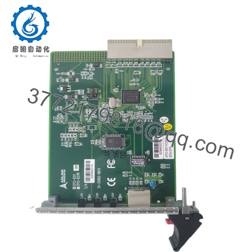
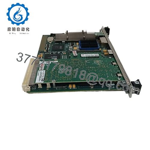
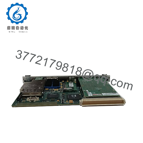
The GE CPCI-5565PIORC-210000 is a CompactPCI Reflective Memory node module that provides deterministic, low-latency data sharing across distributed control systems. It mounts a 5565-series PMC Reflective Memory board on a 3U CompactPCI carrier, commonly used in National Instruments PXI chassis and other cPCI setups for real-time applications.
Writes to local memory automatically broadcast to all other nodes on the fiber ring without processor involvement or software overhead. In field deployments of simulation, data acquisition, and process control systems, engineers choose this module for its reliable performance in noisy industrial environments and its ability to maintain data consistency across up to 256 nodes.
Installation & Configuration Guide
Stage 1: Pre-Installation Preparation (10–15 minutes) ⚠️ Safety First: Notify operations, schedule controlled downtime, verify the system reaches a safe state, perform lockout/tagout on the chassis power, and wait 5 minutes for capacitor discharge. Tools Required: Grounded ESD wrist strap, PH1 or PH2 screwdriver, digital multimeter, wire labels, smartphone for photos. Data Backup: Export current application logic and configuration. Photograph the existing module’s fiber connections, any DIP settings (if present), and terminal layouts. Document node addresses and network topology.
Stage 2: Removing the Old Module (5 minutes)
- Power down the chassis completely.
- Remove the front panel cover or bezel if installed.
- Label and carefully disconnect the fiber optic cables (use dust caps immediately). Do not bend fibers sharply.
- Release the CompactPCI ejector handles or locking tabs and pull the module straight out to avoid damaging backplane pins.
- Inspect the slot for bent pins, dust, or corrosion.

- CPCI-5565PIORC-210000
⚠️ Keep the old module aside as a reference until the new unit runs without issues.
Stage 3: Installing the New Module (10 minutes)
- Wear your ESD strap and work on a grounded surface. Verify the new module part number matches CPCI-5565PIORC-210000 exactly.
- Configuration Clone (Critical): Mirror any jumper or switch settings from the old module photo. Confirm fiber transceiver type (multimode for this -210000 variant).
- Align the module with the slot guides and insert firmly until it seats with an audible click. Secure the ejector handles or retaining screws.
- Reconnect the fiber optic cables to the TX/RX ports (match polarity from your photos). Hand-tighten connectors only.
Self-Checklist: [ ] Model and fiber type match, [ ] Module fully seated, [ ] Fiber connections secure and clean, [ ] No strain on cables.
Stage 4: Power-On & Testing (10–15 minutes) Pre-Power Check: Use a multimeter to verify no shorts on the +3.3 V and +5 V rails to ground. Power-On Steps:
- Apply power to the chassis only (leave field devices disconnected initially).
- Observe module LEDs for normal boot behavior (consult the specific hardware reference for exact LED meanings; green typically indicates link and RUN status).
- Connect to the host system and verify node recognition in your Reflective Memory driver or application software.
- Load or download the existing configuration/logic if needed.
- Perform a dry-run test: write known values to memory addresses and confirm they appear correctly on other nodes with expected latency.
⚠️ Troubleshooting Note: Solid error LED or no link usually points to fiber polarity reversal, dirty connectors, or incompatible multimode fiber distance. Communication timeout often traces back to node address mismatch or ring topology break. If issues persist, power cycle the entire ring after checking all connections.
Frequently Asked Questions (FAQ)
Can this module be hot-swapped under power? No. The design does not support hot-swap on the CompactPCI bus in this configuration. Power down the chassis first. Attempting insertion or removal under power risks damaging the backplane or the module.
Is the CPCI-5565PIORC-210000 obsolete, and is stock genuinely new? This series has reached end-of-life from the OEM, but we maintain new original / new surplus inventory with full traceability. Units come factory sealed or in original packaging where possible. We verify each board through power-on, memory, and basic link tests before shipment.
What is the direct replacement if this exact part is out of stock? The closest functional equivalents are other 5565 family cards in different form factors (such as PCI-5565PIORC or PCIE-5565PIORC), but they require carrier or bus adaptation. Always confirm bus compatibility and fiber type (-210000 is multimode). Contact us with your chassis details for the best match.
Will I lose my programming or configuration when swapping the module? No. Reflective Memory operates as shared memory; the application logic resides in the host controller or software. The new module receives broadcast data once the fiber ring re-establishes. You only need to ensure the node integrates into the existing ring topology.
Why is the price lower than current OEM list pricing? We source through authorized surplus channels and maintain lower overhead than factory-direct channels for discontinued parts. All units undergo inbound verification, functional testing on a cPCI/PXI rack, and parameter checks. Price reflects availability of legacy stock, not quality.
Does this support redundant fiber links? Yes, the 5565 family includes redundant transfer mode for additional error checking, though it halves the effective data rate. Confirm your application requires it before enabling.
Keep these points in mind during your swap and you will avoid most common downtime issues on 5565 Reflective Memory networks. Test videos and inspection photos available upon request. Verify exact compatibility with your system documentation before ordering.


