
 WhatsApp: +86 16626708626
 Email:
  Phone: +86 16626708626
Description
3. Key Technical Specifications
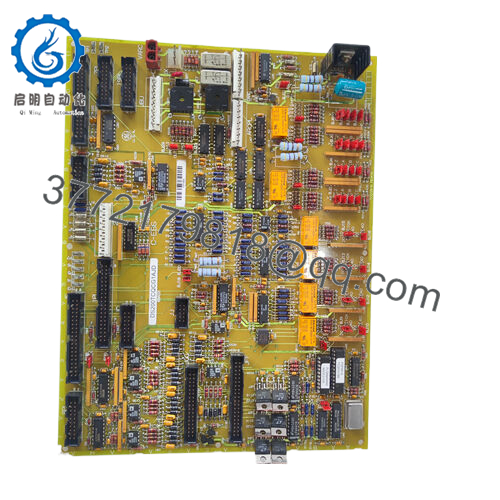
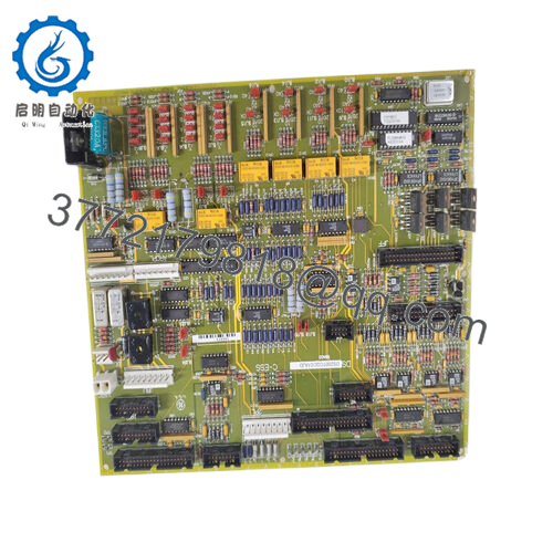
- Function: Analog-to-Digital Multiplexer Daughterboard
- Analog Inputs: 12 total (3 frequency-scaled at 200 kHz/V + 1 MHz carrier over ±5 V; 9 sampled ±5 V via 12-bit successive approximation A/D)
- Analog Outputs: 4 channels, 12-bit resolution, ±10 V into 2 kΩ / 500 pF load
- Digital I/O: 8 ports, registered and interfaced via EPLD to DSPC DSP
- Connectors: XA_ (60-pin high-density), XB_ (40-pin high-density), TBPL (60-pin ribbon cable header)
- Status Indicators: Green IMOK LED, Red FAIL LED
- Interface: EPLD with static RAM for I/O to DSPC processor buses; buffers and filters signals
- Mounting: Plugs directly under DS200DSPC Digital Signal Processor board in VMEbus rack
- Compatibility: LS2100 Static Starter Control; connects to DDTB I/O terminal board via high-density cables
- Standards: UL, CE, CSA
- Weight: 4 oz (113 g)
- Operating Environment: Designed for industrial turbine and drive control cabinets (exact temp range per system manual)

- DS200ADMAH1A
4. Product Introduction
The GE DS200ADMAH1A is an analog-to-digital daughterboard used in the LS2100 static starter control system and compatible Mark V platforms. It mounts directly onto the DS200DSPC processor board and expands I/O capability by providing additional analog signal conversion plus digital interfacing for precise control of thyristor bridges in large motor starters.
Technicians choose this board when the base DSPC requires extra analog inputs for voltage/current feedback, frequency scaling, or auxiliary signals, along with clean analog outputs for external metering or control. The integrated EPLD handles timing and data transfer to the DSP, while the faceplate LEDs give immediate visual status. In field use on gas turbine starting systems or heavy industrial drives, it delivers the signal conditioning needed for reliable SCR firing and protection without custom external hardware.
5. Installation & Configuration Guide
Stage 1: Pre-Installation Preparation (10–15 minutes) ⚠️ Safety First: Notify operations of planned downtime. Apply lockout/tagout to all power supplies feeding the control cabinet. Verify zero voltage on the VMEbus backplane and any connected high-voltage terminal boards. Wait for capacitors to discharge. Tools Required: Grounded ESD wrist strap, small flat or Phillips screwdriver, torque driver for connectors, multimeter, camera or smartphone, laptop with GE toolbox software if needed for verification. Data Backup: Photograph the existing DS200DSPC assembly from multiple angles showing cable routing, connector positions, and LED states. Record any custom jumper or configuration settings on the DSPC. Download any diagnostic logs if the system is still partially powered.
Stage 2: Removing the Old Module (5–10 minutes)
- Power down the entire rack and confirm zero voltage.
- Disconnect the high-density cables from the XA_, XB_, and TBPL connectors on the ADMA board. Label cables if not already marked.
- Remove the DS200DSPC board assembly if required for access (the ADMA sits underneath). Release the board retainers carefully.
- Gently separate the old ADMA daughterboard from the DSPC by releasing the standoffs or connectors without bending pins.
- Inspect the DSPC mating connectors and the backplane for dust, corrosion, or bent pins. ⚠️ Note: Keep the old ADMA board intact and untouched until the new installation runs fault-free through several start cycles.
Stage 3: Installing the New Module (10–15 minutes)
- Verify the replacement board carries the exact DS200ADMAH1A designation and shows no physical damage or bent connector pins.
- Align the daughterboard connectors with the corresponding sockets on the underside of the DS200DSPC. Press firmly and evenly until seated (listen for the mechanical click). Secure any standoffs.
- Reinstall the combined DSPC + ADMA assembly into the VMEbus rack and lock the retainers.
- Reconnect all high-density cables to XA_, XB_, and TBPL exactly as photographed. Apply proper torque to avoid damaging pins. Self-Checklist: [ ] Board fully seated with no gap, [ ] All cables matched and secure, [ ] No strain on connectors, [ ] Faceplate aligned.
Stage 4: Power-On & Testing (15–25 minutes) Pre-Power Check: Measure insulation resistance on I/O cables if high-voltage side is involved. Confirm no shorts on low-voltage supplies. Power-On Steps:
- Restore control power to the rack only (keep main power isolated).
- Observe the ADMA faceplate LEDs: Green IMOK should illuminate steadily; red FAIL must stay off.
- Monitor the DSPC board diagnostics for proper recognition of the ADMA. Check that analog input values and output scaling read correctly in the toolbox or HMI.
- Perform signal simulation or low-level dry tests on connected analog channels and digital I/O.
- Once cleared, bring the system online gradually and verify bridge control feedback during a test start sequence. ⚠️ Troubleshooting Note: Steady red FAIL LED usually indicates a board fault, loose connector, or power issue to the ADMA. Missing analog readings often trace to cable mismatch on XA_/XB_ or incorrect scaling in the DSPC configuration. If the system logs communication errors with the EPLD, reseat the daughterboard.
Typical experienced technician replacement time: 45–60 minutes end-to-end, assuming no wiring repairs.
6. Frequently Asked Questions (FAQ)
Can this daughterboard be replaced while the LS2100 system is powered? No. The DS200ADMAH1A sits directly under the DS200DSPC in the VME rack with live backplane voltages possible. Hot-swapping risks damaging the processor board, corrupting data, or causing uncontrolled SCR firing. Always de-energize the control power first.
Is the DS200ADMAH1A obsolete, and are your units genuinely new? Yes, both the LS2100 series and many Mark V DS200 boards are long obsolete with no new production from GE. Units supplied here are new surplus — genuine factory stock never installed in the field. Each board undergoes visual inspection, connector pin checks, and basic power-up verification with LED status confirmation before shipment. Full test reports available on request.
What is the recommended direct replacement if this board is unavailable? GE does not offer a drop-in current equivalent. Most sites migrate the entire LS2100 control to newer excitation or drive platforms such as the EX2100 or modern static starter controls. This requires significant rewiring, new I/O terminal boards, and software conversion. Plan a full system upgrade assessment rather than piecemeal board swaps to avoid repeated downtime.
Will installing a new DS200ADMAH1A require reconfiguration of the DS200DSPC or loss of existing parameters? No. The ADMA is a passive signal conditioning and multiplexing daughterboard. Setpoints and application code reside on the DSPC. The new board should be recognized automatically, but always verify analog scaling and I/O mapping in the toolbox after installation. Re-learn or confirm any bridge-specific parameters during commissioning.
Why is the price lower than historical GE OEM pricing? These are new surplus boards sourced from excess or decommissioned inventory rather than current manufacture. We perform incoming inspection, connector verification, and functional LED/power testing on each unit. The savings come from avoiding full new-production costs while still delivering tested, warrantied hardware. A 1-year functional warranty applies from shipment.
How do I interpret the LEDs on the ADMA faceplate? Green IMOK means the board is receiving power and the EPLD logic is functioning normally. A lit red FAIL indicates an internal fault on the ADMA, loss of communication with the DSPC, or a configuration mismatch. If FAIL stays on after reseating and power cycle, replace the board.
What manuals should I reference for detailed scaling and wiring? Use GEH-6373 (LS2100 system manual) and GEI-100218 for the ADMA board specifics. They cover connector pinouts, analog input frequency scaling, output drive capability, and troubleshooting flowcharts. Always cross-check against your site-specific drawings before making wiring changes.


