
 WhatsApp: +86 16626708626
 Email:
  Phone: +86 16626708626
Description
3. Key Technical Specifications
| Parameter | Value |
|---|---|
| Manufacturer | GE General Electric |
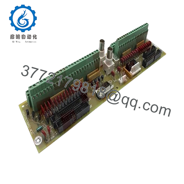
| Model Number | DS200CTBAG1ADD |
| Product Family | Mark V Speedtronic |
| Product Type | Terminal Board |
| Mounting Method | Rack/Panel Mounted |
| Application | Gas and Steam Turbine Control |
| System Compatibility | GE Mark V Control Systems |
| Operating Voltage | Typically 24 V DC control environment |
| Communication Interface | Backplane control bus integration |
| PCB Coating | Industrial conformal-coated board |
| Operating Temperature | 0 °C to 60 °C typical cabinet environment |
| Storage Temperature | −40 °C to +85 °C |
| Humidity Rating | 5% to 95% non-condensing |
| Condition | New Original / New Surplus |
| Availability | Limited surplus inventory |
| Warranty | 12 Months |
4. Product Introduction
The GE DS200CTBAG1ADD is a Mark V Speedtronic terminal board used in GE turbine control systems for signal termination and control interface distribution. It is commonly installed in gas turbine, steam turbine, and power generation control cabinets where stable I/O signal handling is required.
In field deployments of Mark V systems, these boards are often replaced during lifecycle extension projects or emergency shutdown recovery. Engineers typically choose this revision when maintaining existing Mark V infrastructure because it avoids larger migration costs associated with Mark VI or third-party retrofit platforms.

- DS200CTBAG1ADD
5. Installation & Configuration Guide
Stage 1: Pre-Installation Preparation (Estimated Time: 10 Minutes)
⚠️ Safety First
- Notify operations and obtain shutdown approval.
- Verify turbine and auxiliary systems are in a safe state.
- Apply lock out/tag out (LOTO) procedures.
- Disconnect cabinet power and wait at least 5 minutes for capacitor discharge.
Tools Required
- ESD wrist strap
- PH1 screwdriver
- Fluke 115 multimeter
- Wire labels
- Smartphone or inspection camera
- Flashlight for cabinet inspection
Data Backup
- Export current control logic and alarm history from the HMI or engineering workstation.
- Record cabinet slot position.
- Photograph all wiring and terminal layouts.
- Document any jumper positions or field modifications.
⚠️ Older Mark V cabinets often contain undocumented field changes from previous outages. Never assume factory-default wiring.
Stage 2: Removing the Old Module (Estimated Time: 5–10 Minutes)
- Remove the cabinet cover or front bezel.
- Label every field wire before disconnecting it.
- Disconnect terminal wiring carefully. Do not pry terminals sideways.
- Release mounting hardware or retaining clips.
- Pull the board straight out to avoid damaging connector pins.
- Inspect the backplane and connector area for:
- Bent pins
- Carbon tracking
- Dust buildup
- Heat discoloration
⚠️ Do not discard the old board immediately. Keep it beside the cabinet during commissioning. I’ve seen technicians discover one missed jumper setting after two hours of troubleshooting.
Stage 3: Installing the New Module (Estimated Time: 10 Minutes)
- Wear a grounded ESD strap before opening the anti-static bag.
- Verify the exact model number: DS200CTBAG1ADD.
- Compare board revision labels carefully.
Configuration Clone (Crucial)
- Replicate all jumper settings exactly.
- Verify terminal orientation and shielding grounds.
- Confirm any address-select jumpers match the original board.
❗ This is one of the most common installation mistakes. A single misplaced jumper can create intermittent faults that only appear under load.
- Insert the board evenly into the mounting position.
- Ensure the board seats fully into the connector.
- Tighten mounting screws evenly without overtightening.
- Reconnect field wiring using proper torque.
Self-Checklist
- Model number matches
- Jumpers copied correctly
- Wiring secure
- Grounding intact
- Board fully seated
Stage 4: Power-On & Testing (Estimated Time: 10–15 Minutes)
Pre-Power Check
- Use a multimeter to verify no shorts exist on the 24 V DC rail.
- Check cabinet grounding continuity.
- Verify no loose conductors remain inside the enclosure.
Power-On Steps
- Energize the control rack only.
- Observe board indicators and cabinet diagnostics.
- Verify communication with the Mark V controller.
- Confirm all expected I/O points appear correctly.
- Perform dry-run signal simulation before returning field devices to service.
Functional Testing Performed During Our QC Process
- Power-on self-test on a genuine GE Mark V test rack
- I/O signal simulation
- Communication verification
- 24-hour thermal stability run
- Insulation resistance testing using 500 V Megger (>10 MΩ)
- Visual inspection for rework marks or corrosion
- Firmware and revision documentation
- ESD-safe packaging and final QC sign-off
Test photos and power-up videos are available upon request.
⚠️ Troubleshooting Note
- Solid fault indicators usually point to connector seating or backplane communication issues.
- Intermittent faults often trace back to loose terminal wiring or grounding problems.
- If the cabinet suddenly reports multiple I/O failures, inspect the backplane connector before replacing additional modules.
6. Frequently Asked Questions (FAQ)
Q1: Can I hot-swap the DS200CTBAG1ADD while the cabinet is energized?
No. The Mark V platform was not designed for casual hot-swapping of these boards. Pulling the module under power can arc the backplane connector or damage adjacent circuitry. Shut the cabinet down properly first.
Q2: Is the DS200CTBAG1ADD obsolete?
Yes. The GE Mark V series is considered legacy equipment. OEM production ended years ago, so most available inventory today comes from surplus stock, plant spares, or refurbishment channels.
That said, many power plants still operate Mark V systems because replacing the entire control platform requires major outage planning and validation work.
Q3: Is this unit genuinely new or refurbished?
This listing is for New Original / New Surplus inventory unless otherwise specified.
That means:
- No prior field installation
- Original PCB condition
- Stored as industrial spare inventory
However, due to age, packaging may show shelf wear. We inspect every unit for oxidation, connector damage, and storage-related deterioration before shipment.
Q4: What happens to my control logic when I remove the old board?
The DS200CTBAG1ADD itself does not normally store primary turbine logic like a CPU module would. Most logic resides elsewhere in the Mark V controller architecture.
Still, always back up the system before maintenance. I’ve seen sites lose undocumented configuration settings because someone assumed “this board is only passive.”
Q5: What is the direct replacement if this module is unavailable?
There is not always a simple drop-in replacement for Mark V boards. GE revisions can differ electrically even when the connector layout looks identical.
Verify:
- Board revision suffix
- Firmware dependencies
- Cabinet revision
- Terminal assignment differences
Never substitute “close enough” Mark V boards without checking documentation first.
Q6: Why are surplus GE Mark V boards expensive even though the platform is old?
Because downtime costs more than hardware.
A turbine trip can cost tens of thousands of dollars per hour in lost generation. Plants often pay premium prices for verified spare boards that can restore operation immediately instead of waiting through a migration project.
Q7: What causes most replacement failures during installation?
Three things show up constantly in the field:
- Incorrect jumper replication
- Bent backplane pins
- ESD damage during handling
❗ I once watched a technician install a replacement board without an ESD strap during winter conditions. The board powered up for three seconds, then failed permanently. That mistake turned a scheduled maintenance window into a 14-hour outage.
Keep these checks in mind and you’ll save yourself 90% of typical rework time.


