
 WhatsApp: +86 16626708626
 Email:
  Phone: +86 16626708626
Description
Key Technical Specifications
| Parameter | Value / Feature Specification |
| Part Number | DS200DCFBG1BGB |
| Functional Acronym | DCFB (DC Power Feedback Board) |
| Primary System Family | GE Mark V Turbine Control & Industrial Drives |
| Input Power Voltage | 38 VAC to 115 VAC (Control Power Transformer supply) |
| DC Output Voltage Rails | +5 VDC (Logic), ±15 VDC (Analog), ±24 VDC (Relay/I/O) |
| Auxiliary Output | 115 VAC output for cabinet cooling fans |
| Signal Monitoring Inputs | Armature current/voltage, field current, phase sequence, motor temp |
| On-Board Hardware | 13 configurable jumpers, 7 DIP switch blocks |
| Status Indicators | 2 Red Diagnostic LEDs (CR51, CR55) and 1 High-Voltage Neon Light (LT1) |
| Connectors & Testpoints | 18 plug connectors, 9 stab connectors, 5 voltage/signal test points |
| Operating Temperature | −40°C to +70°C (−40°F to +158°F) |
| Compatible Platforms | EX2000, DC2000, AC2000, CB2000, ME2000, FC2000 drives |
Product Introduction & Supply Chain Strategy
The GE DS200DCFBG1BGB functions as the vital DC power generation and feedback regulation engine inside GE Speedtronic Mark V turbine control panels and EX2000/DC2000 industrial drive cabinets. It steps down incoming control power to distribute regulated logic power rails (+5V, ±15V, ±24V) while dynamically monitoring armature current, line voltages, and thermal status for connected power conversion bridges.
This product is a Brand New Surplus unit. It is not used, not pulled from a decommissioned plant, and not refurbished. All modules undergo rigorous quality verification to ensure OEM-level reliability. Stocking this critical component as New Surplus delivers immediate capital protection. Because original equipment manufacturers have phased out production for legacy Mark V hardware, plant operators face catastrophic lead times during an unannounced power board failure. Choosing genuine New Surplus bypasses months of OEM backorder delays while totally eliminating the severe premature failure risks, hidden degradation, and thermal stress compromises typical of refurbished or second-hand components.
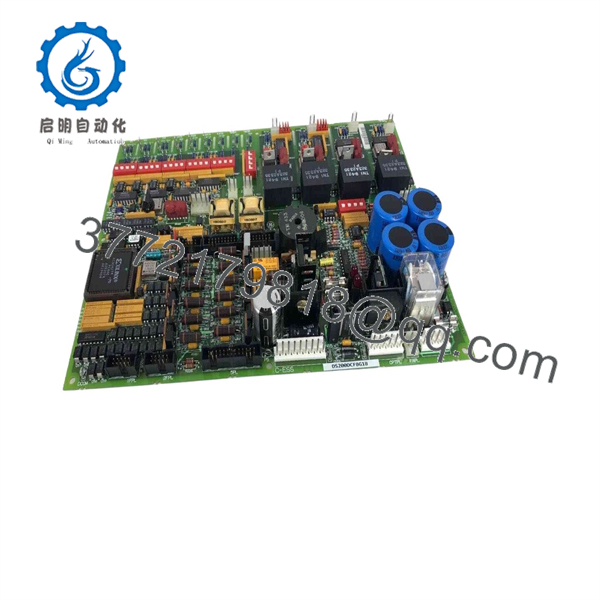
DS200DCFBG1BGB
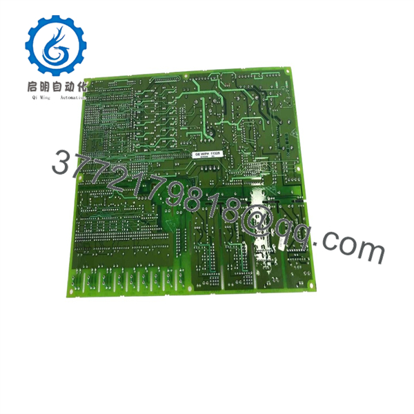
DS200DCFBG1BGB
Installation & Configuration Guide
1.Pre-Installation Preparation & Safety:Prerequisite.
Enforce complete Lock-Out/Tag-Out (LOTO) procedures on the control cabinet. Disconnect all 120 VAC power sources and wait a minimum of 5 minutes to allow large power supply capacitors on the backplane to discharge completely. Put on a grounded ESD wrist strap (1 MΩ resistance) before opening the ESD-protective bag. Take high-resolution photos of the legacy DS200DCFB board’s jumper settings (JP1–JP13), DIP switch configurations, and terminal wiring layouts for exact visual documentation.
2.Removal of Legacy Module:
Unplug all 18 ribbon and cable connectors and disconnect the 9 stab connectors from the board face. Label every wire bundle with its corresponding connector ID. Remove the retaining screws securing the board to the 6U rack chassis. Carefully slide the board straight outward along the guide rails to prevent bending or shearing the 96-pin backplane connector pins.
3.Hardware Cloning & Module Insertion:
Match every jumper (JP1 through JP13) and the 7 DIP switch blocks on the new DS200DCFBG1BGB unit to mirror your original board’s settings identically. Verify zero pin deformation on the rear connector. Align the new board with the rack chassis guide rails and push firmly until the 96-pin connector fully seats into the backplane with an audible engagement. Secure the board using the M4 mounting screws (torque to 0.8 N·m).
4.Re-wiring & Power-On Diagnostics:
Reconnect all stab and plug connectors to their designated headers. Torque terminal block screws (TB3/TB4) to 0.6 N·m. Re-apply main incoming power. Verify that the power-on self-test activates: solid green status indicators show normal operation, while flashing red LEDs indicate a hardware/configuration fault. Measure the onboard voltage test points using a calibrated multimeter to confirm stable +5 VDC, +15 VDC, and −15 VDC power rails.
Firmware/Software Versions & Upgrade Notes
- Revision Code Parsing: The part number DS200DCFBG1BGB explicitly decodes the hardware generation.
G1designates the original board design,Bindicates functional revision level 1,Grepresents functional revision level 2, and the finalBmarks the artwork revision. - Firmware Dependencies: This board hosts hardware-level signal conditioning and power control routines. It interfaces directly with the primary Speedtronic Mark V controller board (SDCC or LDCC). Always verify that your SDCC controller firmware is compatible with Revision G1B hardware before commissioning.
- Backward Compatibility Caution: Installing a higher artwork revision (e.g., revision BKC or later) introduces 13 active jumpers instead of earlier 12-jumper layouts. Blindly swapping revision levels without cross-checking hardware jumper functions can disrupt gate pulse timing or cause false overcurrent trips on DC drive systems.
- Firmware Modification Hazard: Do not attempt flash upgrades or EEPROM swaps on power feedback boards during emergency maintenance shutdowns. Keep hardware revisions consistent with existing plant baseline documentation to prevent bus communication timeouts.
Frequently Asked Questions (FAQ)
Why is this New Surplus unit priced higher than refurbished boards on the market, but lower than OEM list prices?
Our pricing reflects the true total cost of ownership (TCO). Refurbished boards are sourced from scrap yards or failed plants, featuring aged electrolytic capacitors and thermal stress that drastically lower mean time between failures (MTBF). Our New Surplus units are 100% genuine, un-used OEM inventory kept in climate-controlled environments. You pay a small premium over used parts to eliminate the risk of a $50,000-per-hour unscheduled plant shutdown while saving significantly off original manufacturer list pricing.
Are these DS200DCFBG1BGB boards truly brand new and unused?
Yes. Every unit is guaranteed Original New Surplus. They come directly from surplus utility reserves, cancelled project spares, or verified OEM distribution channels. They have zero operating hours, zero soldered repairs, and clean gold backplane contacts.
Since GE has discontinued (EOL) the Mark V system, how do you verify board quality?
Every incoming board undergoes a standardized multi-step SOP quality inspection. We test electrical insulation, verify ground continuity, inspect traces under magnification for micro-fractures, and run live power-on self-tests on dedicated test racks to verify the accuracy of the onboard +5V, ±15V, and ±24V regulation rails.
Can I hot-swap the DS200DCFBG1BGB board while the drive or turbine is running?
No. Attempting to hot-swap this card will cause immediate arc flashing, destroy backplane logic pins, and trip the entire turbine control system. The DCFB board carries high-voltage feedback signals and primary AC input lines (up to 115 VAC). Always perform a full system shutdown and follow LOTO guidelines before removal.
What happens if I forget to set the DIP switches and jumpers before powering on?
Incorrect jumper or DIP switch positions can cause incorrect feedback signal scaling, improper field excitation parameters, or immediate system fault trips upon bootup. Always clone the physical jumper positions (JP1 through JP13) from your old card to the new card prior to rack installation.
What warranty coverage comes with this New Surplus board?
We back this module with a full 1 year replacement warranty (depending on your service level agreement). If the board fails under normal operating conditions within the warranty window, we immediately dispatch a replacement unit from our emergency reserve stock to ensure zero prolonged downtime.



