
 WhatsApp: +86 16626708626
 Email:
 Phone: +86 16626708626
Description
Core Product Summary
The GE DS200DCFBG1BKC is a DCFB power-supply and feedback board for GE industrial drive and excitation systems, including DC2000, CB2000, EX2000, FC2000, GF2000, ME2000, and AC2000 IGBT drive applications. It receives 38 V AC and 115 V AC power from the control power transformer (CPT), produces control-level DC supplies for the drive, and supplies 115 V AC power for enclosure cooling fans.
The board also conditions voltage and current feedback for the SDCC/LDCC drive-control board. Its voltage-controlled oscillator (VCO) circuits convert measured AC-line, DC-bridge, motor-voltage, and shunt signals into frequency signals, while its gate-array-based circuits generate the firing signals required by the armature and field SCR bridge. The BKC designation identifies a specific revision configuration within the DS200DCFBG1B board family and must be configured with the same jumper and DIP-switch settings as the board it replaces.
Key Technical Specifications
| Parameter | Specification |
|---|---|
| Manufacturer | General Electric (GE) |
| Product designation | DS200DCFBG1BKC |
| Functional acronym | DCFB |
| Product type | DC feedback power supply board |
| Board family | GE Mark V / DS200 |
| Board group | G1 |
| Functional revision | B |
| Supported drive applications | DC2000, CB2000, EX2000, FC2000, GF2000, ME2000, and AC2000 IGBT drive applications |
| Input power | 38 V AC (±10%) and 115 V AC from the control power transformer (CPT) |
| DC outputs | +5 V DC, +15 V DC, -15 V DC, +24 V DC, and -24 V DC |
| +24 V DC output rating | 3 A |
| -24 V DC output rating | 1 A |
| ±15 V DC output rating | 0.8 A each; 0.25 A of each output is available for external loading |
| +5 V DC output rating | 4 A |
| VCO nominal output frequency | 250 kHz |
| VCO output-frequency range | 0 to 500 kHz |
| Motor-voltage analog feedback | 0 to 5 V, biased at 2.5 V |
| On-board configuration | 12 configurable jumpers; 13 on revision BKC and later; 7 DIP switches |
| Diagnostic indicators | Two red LEDs (CR51 and CR55), one neon lamp (LT1), and five test points |
| Protective devices | Three fuses: FU1, FU2, and FU3 |
| Connectors | 18 plug connectors and 9 stab connectors |
| Firmware | The DS200 board designation indicates that the board does not contain firmware |
| Applicable manual | GEI-100028 |
The DCFB functional description, power and feedback functions, supported applications, and manual reference are consistently identified for the DS200DCFBG1BKC.
Engineering Selection Highlights
- The DS200DCFBG1BKC is a DCFB power-supply and feedback board, not a standalone controller → its suitability depends on the connected SDCC/LDCC drive-control board and the intended drive application.
- It requires 38 V AC and 115 V AC input power from the CPT → the control-power-transformer arrangement must provide both supplies before the board can perform its power-conversion and feedback functions.
- The board provides +5, ±15, and ±24 V DC control-level outputs → its published current ratings establish the available capacity for connected drive-control circuits and limited external loads.
- Its VCO circuits convert AC-line, DC-bridge, motor-voltage, and shunt signals into frequency feedback for the SDCC/LDCC board → correct switch scaling is essential to valid feedback and protection functions.
- The board includes SCR gate-firing control circuits that send gate-pulse signals to the DS200PCCA Power Connect Card → the associated PCCA and bridge hardware must be part of the intended drive configuration.
- Jumper and DIP-switch positions are application-specific → a replacement board must be configured to match the original board unless the applicable instructions direct otherwise.
- The BKC suffix identifies a specific revision configuration within the DCFB G1 board family → all characters in the catalog number should be matched when ordering or replacing the board.
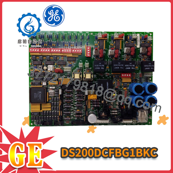
DS200DCFBG1BKC
System Compatibility & Integration Requirements
| Item / Dependency | Verified Compatibility or Requirement | Practical Note |
|---|---|---|
| Drive applications | DC2000, CB2000, EX2000, FC2000, GF2000, ME2000, and AC2000 IGBT drive applications | The board is intended for these GE drive and excitation-system applications. |
| Drive-control interface | SDCC or LDCC board | Feedback, synchronization, SCR-control, and power-supply signals interface through connector 1PL and related connections. |
| Power-connect interface | DS200PCCA Power Connect Card | The DCFB sends SCR gate-pulse signals to the PCCA through connector 5PL. |
| Input power source | Control power transformer (CPT) | The board receives 38 V AC and 115 V AC from the CPT. |
| AC-line feedback scaling | DIP switches SW1, SW2, and SW3 | These switches scale the line-voltage feedback used for phase-loss detection, sequence detection, and synchronization. |
| DC feedback scaling | DIP switches SW4, SW5, and SW6 | These switches scale DC-bridge voltage, motor-voltage VCO, and analog motor-voltage feedback circuits. |
| Current-transformer interface | AC line current transformers on lines L1 and L3 | DIP switch SW7 selects the ACCT burden resistance according to the rated drive current and CT turns ratio. |
| High-voltage interface | SHVI or SHVM board, where required | SHVI/SHVM attenuation is required above specified AC or DC voltage thresholds, depending on the application. |
| Replacement configuration | Original jumper and DIP-switch settings | The replacement board’s jumpers and switches must match the replaced board unless instructions state otherwise. |
These dependencies are documented for the DS200DCFBG1B board family and apply to the DS200DCFBG1BKC revision configuration.
Dimensions, Mounting & Connection Notes
| Item | Verified information |
|---|---|
| Board format | DS200 printed-circuit board for GE drive-control equipment |
| Mounting context | Normally installed in the board carrier behind the drive-control card; some EX2000 applications may use a different location |
| Board connectors | 18 plug connectors and 9 stab connectors |
| Configuration devices | 12 configurable jumpers, or 13 on revision BKC and later; 7 DIP switches |
| Protective devices | Three fuses: FU1, FU2, and FU3 |
| Diagnostic devices | Two red LEDs, one neon lamp, and five test points |
| Replacement practice | Match all jumper and DIP-switch positions to the replaced board; do not remove, install, or reconnect boards while the drive is energized |
The DCFB board is normally accessed by opening the equipment cabinet, releasing the board-rack lock tabs, and tilting the front board carrier forward and downward. The manufacturer’s replacement procedure requires the drive to be de-energized, capacitors allowed to discharge, and the absence of voltage confirmed before board handling. Boards must be treated as static-sensitive and handled using grounding precautions.
Detailed Product Overview
The GE DS200DCFBG1BKC is the BKC revision configuration of the DCFB power-supply board used in GE DC2000, CB2000, EX2000, FC2000, GF2000, ME2000, and AC2000 IGBT drive applications. It is a board-level power and feedback interface: it takes AC control power from the CPT, creates regulated DC supplies for the drive-control electronics, conditions drive feedback signals, and participates in the SCR firing chain.
The board receives 38 V AC and 115 V AC from the CPT. The 38 V AC input is full-wave rectified and filtered to create unregulated ±24 V DC supplies. The +24 V DC output is rated at 3 A and the -24 V DC output at 1 A. On-board regulators derive ±15 V DC from these supplies; each ±15 V DC output is rated at 0.8 A, with 0.25 A available for external loading. The board also produces a +5 V DC, 4 A output from the +24 V DC supply. When the +5 V DC supply is in regulation, the /PSEN signal remains low; if it leaves regulation, /PSEN goes high and generates a microprocessor reset on the SDCC/LDCC board.
Feedback processing is a central function of the DCFB board. Its VCO circuits convert input voltages into frequency signals with a nominal 250 kHz output and a 0 to 500 kHz range depending on input voltage. These frequency signals are sent to the SDCC/LDCC board through connector 1PL and represent SCR-bridge AC input voltage, output-bridge voltage, motor voltage, and millivolt signals from field and armature shunts. A separate motor-voltage attenuation circuit provides a 0 to 5 V analog representation of motor voltage, biased at 2.5 V.
The board also processes AC-line voltage and current. Amplifier circuits process line-to-line voltages and provide signals used for power-bridge SCR-failure detection and, where applicable, SCR-firing synchronization. Where ACCTs are installed on drive input lines L1 and L3, DIP switch SW7 selects the burden resistance based on the drive’s rated current and CT turns ratio. The SDCC/LDCC board uses the resulting ACCT signals for commutation-failure and AC instantaneous-overcurrent checks.
The SCR firing path is equally significant. A gate-array circuit on the DCFB receives control signals from the SDCC/LDCC board and is programmed at power-up by a serial PROM. Its 5 V outputs are amplified into the power level required by the forward and reverse gate-pulse transformers on the DS200PCCA Power Connect Card. Firing power is withheld until the gate array is programmed and the 5 V supply is regulated, reducing the possibility of spurious firing signals.
Configuration is not optional. The board includes 12 configurable jumpers—13 on revision BKC and later—and seven DIP switches. Most positions are factory-set, and the controller’s test data sheets record the required positions. When replacing a DCFB board, the new board’s jumpers and switches must match the original configuration unless the applicable instructions state otherwise. The board provides two red LEDs, a neon lamp, five test points, and three fuses for power-supply protection and diagnostics. Fuses FU1, FU2, and FU3 are the only user-replaceable components; failure of any other board component requires replacement of the complete board.
Applications & System Role
In a GE drive-control architecture, the DS200DCFBG1BKC performs three closely related functions: it generates control-level power, conditions operating feedback, and supports SCR bridge firing. The control-level supplies power the SDCC/LDCC and associated control circuitry, while the 115 V AC output is designated for enclosure cooling fans.
The feedback circuits convert AC-line voltage, DC-bridge voltage, motor voltage, and shunt-based current signals into frequency or analog signals for the SDCC/LDCC board. These signals support line synchronization, phase-loss and phase-sequence detection, commutation-failure and instantaneous-overcurrent checks, and drive-control feedback. The board’s gate-array circuit receives control commands from the SDCC/LDCC board and produces gate-pulse signals for the SCR bridge through the PCCA Power Connect Card.
For EX2000 applications, the board is used for a different purpose than in a drive application. The manufacturer’s documentation identifies this distinction explicitly, so the intended EX2000 configuration should govern the applicable wiring, scaling, and configuration settings.
FAQ
What is the GE DS200DCFBG1BKC?
It is a GE DCFB DC feedback power-supply board used in DC2000, CB2000, EX2000, FC2000, GF2000, ME2000, and AC2000 IGBT drive applications.
What does DCFB mean?
DCFB is the board functional acronym for the DS200DCFB power-supply and feedback board family.
What power does the DS200DCFBG1BKC receive?
It receives 38 V AC and 115 V AC input power from the control power transformer (CPT).
Which DC supplies does it generate?
It generates +5 V DC, +15 V DC, -15 V DC, +24 V DC, and -24 V DC control-level supplies.
What is the 115 V AC output used for?
It supplies 115 V AC power to the enclosure cooling fans.
Which board receives its feedback signals?
The SDCC or LDCC drive-control board receives the feedback and control signals through the DCFB board’s connector interfaces.
Which board receives its SCR gate-pulse signals?
The DS200PCCA Power Connect Card receives the gate-pulse signals through connector 5PL.
Does the DS200DCFBG1BKC contain firmware?
No. The DS200 designation indicates that the board does not contain firmware; its gate-array circuit is programmed at power-up by a serial PROM.
What must be matched when replacing the board?
The replacement board’s jumper and DIP-switch positions must match those of the board being replaced, unless the applicable instructions state otherwise.
Which components can be replaced in the field?
Fuses FU1, FU2, and FU3 are the only end-user-replaceable components on the DCFB board; any other component failure requires replacement of the board as a unit.



