
 WhatsApp: +86 16626708626
 Email:
  Phone: +86 16626708626
Description
Key Technical Specifications
| Parameter | Value |
|---|---|
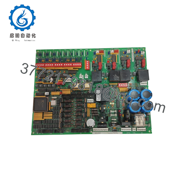
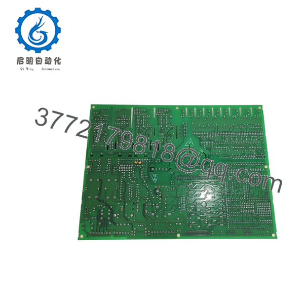
| Model | DS200DCFBG2BNC |
| Brand | GE (GE Fanuc) |
| Series | Speedtronic Mark V (DS200) |
| Product type | DC Power Feedback Board (DC2000) |
| Primary application | GE Mark V turbine control DC power regulation and feedback |
| Input voltage range | 12–48 V DC (typical operating: 12 V / 24 V / 48 V) |
| Input terminals | 3-core, 7.62 mm spacing standard industrial terminals |
| No-load power | 2.16 W @ 24 V DC |
| Internal components | 7 DIP switches, 5 TP test points, 12 jumpers, 3 fuses |
| Fuse function | Power protection; fuse fault indicated by LED |
| Redundancy support | Supports Mark V simplex, dual, and triple-redundant configurations |
| Mounting | Mark V DS200 backplane slot with faceplate connectors |
| ESD sensitivity | Static-sensitive (handle with ESD strap and ESD bag) |
| Condition | New Surplus / Tested |
| Warranty | 3 years (typical for tested board) |
Product Introduction
GE DS200DCFBG2BNC is a DC2000 DC Feedback Power Board designed for GE Speedtronic Mark V turbine control systems. It provides regulated DC power feedback and voltage regulation for control electronics in gas and steam turbine applications.
This board is chosen when replacing a failed power feedback card in a Mark V cabinet. The built-in DIP switches, jumpers, and test points allow precise configuration and diagnostics, while the 3-fuse protection reduces downtime from power faults.

- DS200DCFBG2BNC
- DS200DCFBG2BNC
Troubleshooting Quick Reference
| Symptom | Possible Cause | Relevance to this Part | Quick Check Method | Recommendation |
|---|---|---|---|---|
| LED fuse fault lit | Blown fuse from overcurrent or short | ✅ High | Visually inspect 3 fuses; measure continuity with multimeter | Replace fuse and find root cause; replace board if fuse blows again |
| No output voltage / board dead | Input power failure or board fault | ✅ High | Measure 12–48 V DC at input terminals; check PSU and wiring | Replace board only after confirming input power is stable |
| Voltage drift or instability | Jumper/DIP misconfiguration or component failure | ✅ High | Verify DIP switch and jumper settings against OEM manual | Restore correct config; replace board if drift persists |
| Intermittent power loss | Poor seating or backplane contact issue | ✅ Medium | Reseat board firmly; inspect edge connector and pins | Clean connector and reseat; replace if fault returns |
| Controller reports power fault | Backplane communication or config mismatch | ✅ Medium | Check diagnostic buffer and board revision in software | Match board revision and firmware range; reseat if needed |
| Multiple system boards fail | Overvoltage from this board | ✅ High | Measure output rails; check for overvoltage on backplane | Replace this board immediately; inspect other boards for damage |
⚠️ ESD Warning: This is a static-sensitive board. Wear a grounded wrist strap and handle in an ESD-safe area. I once watched a tech handle a $2,000 card in the dead of winter without a strap. Powered it up, and it immediately let the magic smoke out. Use an ESD strap.
⚠️ Fuse Warning: The 3 fuses protect the board. If any fuse blows, check wiring and load before replacing. Repeated blowouts indicate a downstream short or overcurrent condition.
Contact technical support with photos of the board, fuse status, LED indicators, input/output voltage measurements, and controller diagnostic logs if the fault is unclear.
Frequently Asked Questions
Q: Is DS200DCFBG2BNC a direct replacement?
A: Yes within the same Mark V cabinet generation, but verify board revision and jumper/DIP switch settings. Different revisions can have altered configurations or pinouts.
Q: Can I hot-swap this power board?
A: No. Power down the rack before swapping. Hot-swapping can cause arcing, damage the backplane, or trigger protection trips in the turbine system.
Q: Will my configuration stay intact after replacement?
A: Part of the config is set via DIP switches and jumpers on the board, not stored in flash. Take a clear photo of the old board’s switches and jumpers before removal, then mirror the exact configuration on the new unit.
Q: What condition is this part in?
A: This listing is New Surplus / Tested. It is not factory-sealed OEM fresh, but it should pass visual inspection and live functional tests. Test reports, photos, and voltage logs are available on request.
Q: Why is it cheaper than factory-direct?
A: Surplus stock comes from excess inventory, decommissioned units, or unused spares. Pricing reflects sourcing, not a claim that the part is newer than OEM stock.
Q: What should I verify before installation?
A: Confirm board revision, DIP switch positions, jumper settings, input voltage range (12–48 V DC), and terminal wiring. Don’t wire from memory—even similar models can have altered pinouts. Always check the manual.
Also calculate total rack backplane power consumption and leave a 20% buffer. I’ve seen projects where a tech swapped a module and the rack power supply browned out because the new board drew more current.
Q: How do I know the board is actually bad?
A: Look for blown fuses that keep blowing, no output voltage despite stable input, voltage drift after config correction, or system-wide power faults traced to this board. If diagnostics still point to the board after those checks, replacement is justified.
Q: What do the DIP switches and jumpers control?
A: They set voltage ranges, feedback scaling, and protection thresholds. The exact mapping is in the OEM manual—document the original settings before any change. Misconfiguring these can cause overvoltage or instability.


