
 WhatsApp: +86 16626708626
 Email:
  Phone: +86 16626708626
Description
3. Key Technical Specifications
| Parameter | Value |
|---|---|
| Manufacturer | General Electric |
| Model | DS200DDTBG1A |
| Product Type | LCI Auxiliary I/O Terminal Board |
| Series | Mark V Speedtronic / LS2100 |
| Primary Function | Auxiliary I/O signal termination and conditioning |
| Companion Board | DS200ADMA Analog-to-Digital Module |
| Host Board | DS200DSPC Digital Signal Processor Control Board |
| Power Supply | +5 VDC supplied by the ADMA board |
| Analog Inputs | High-voltage AC, CT, LEM, and configurable 4–20 mA inputs |
| Analog Outputs | Buffered voltage outputs and 4–20 mA current outputs |
| Test Points | 33 onboard test points |
| Jumpers | 12 configurable jumpers for signal assignment |
| Status Indicators | 17 onboard LEDs |
| Mounting | Control cabinet terminal board |
| Typical Applications | GE Speedtronic Mark V Load Commutated Inverter (LCI) systems for gas turbine starting and drive control |
The board performs signal conditioning, scaling, buffering, and electrical isolation before passing field signals to the DSP through the ADMA module.
4. Product Introduction
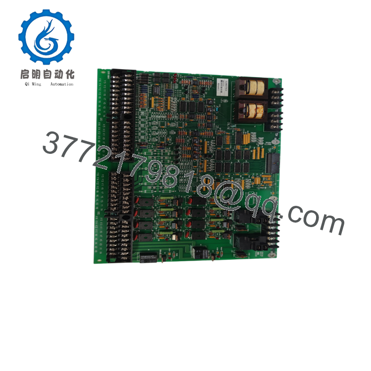
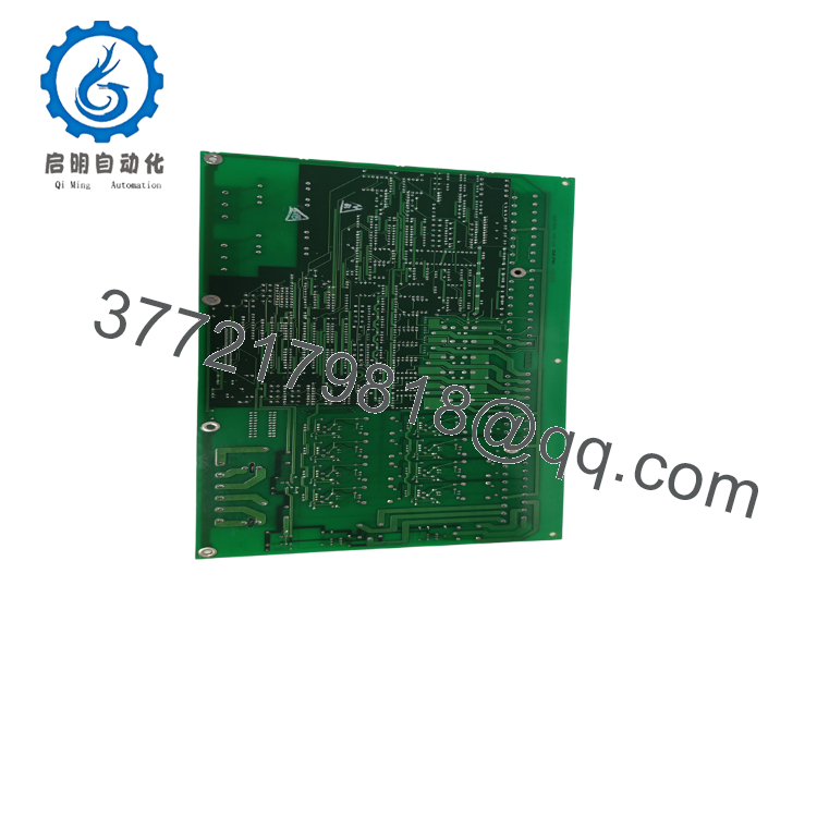
The GE DS200DDTBG1A is an LCI Auxiliary I/O Terminal Board used in GE Mark V Speedtronic and LS2100 Load Commutated Inverter (LCI) control systems. It serves as the interface between field devices and the digital signal processor by conditioning analog and digital signals for reliable acquisition and processing.
The board connects directly to the DS200ADMA analog-to-digital module mounted on the DS200DSPC processor board. It supports high-voltage AC measurements, current transformer (CT) inputs, Hall-effect current sensors, configurable 4–20 mA loops, and buffered analog outputs. An onboard electronic identification memory stores board identification and hardware revision data, simplifying maintenance and system recognition.

- DS200DDTBG1A
- DS200DDTBG1A
5. Installation & Configuration Guide
Stage 1 – Pre-Installation Preparation (10 Minutes)
⚠️ Safety First
- Notify plant operations of the scheduled outage.
- Perform Lock-Out/Tag-Out (LOTO).
- Remove all cabinet control power.
- Wait at least 5 minutes for capacitor discharge.
- Verify zero voltage using a calibrated multimeter.
Tools Required
- ESD wrist strap
- Phillips screwdriver
- Fluke 115 or equivalent multimeter
- Wire markers
- Smartphone for wiring documentation
- Engineering laptop with applicable GE Mark V maintenance software
Data Backup
- Photograph every terminal connection.
- Record jumper positions.
- Document wiring labels.
- Record board revision.
- Save existing system configuration if available.
Stage 2 – Removing the Existing Board (5–10 Minutes)
- Disconnect all field wiring after labeling.
- Remove ribbon cables connected to the ADMA board.
- Release the mounting hardware.
- Remove the board carefully without bending connectors.
⚠️ Retain the original board until the replacement has successfully completed commissioning.
Inspect:
- Backplane connectors
- Ribbon cable condition
- Terminal block integrity
- Signs of overheating
- Dust accumulation
Stage 3 – Installing the New Board (10 Minutes)
- Wear an ESD wrist strap.
- Verify the complete part number:
DS200DDTBG1A - Confirm compatibility with the installed ADMA and DSPC boards.
- Install the board securely.
- Reconnect ribbon cables.
- Restore all field wiring.
- Restore jumper settings exactly as documented.
Installation Checklist
- ☑ Correct model installed
- ☑ Ribbon cables fully seated
- ☑ Jumpers duplicated
- ☑ Wiring verified
- ☑ Ground connection confirmed
Stage 4 – Power-On & Commissioning (15 Minutes)
Before Applying Power
- Verify +5 V supply integrity.
- Check field wiring for shorts.
- Confirm ribbon cable orientation.
Commissioning Steps
- Energize the Mark V control cabinet.
- Verify the board status LED.
- Confirm communication with the DSPC processor.
- Verify analog input scaling.
- Test CT and LEM input channels.
- Verify 4–20 mA inputs and outputs where used.
- Review diagnostic alarms.
- Complete functional testing before returning the system to service.
⚠️ Troubleshooting
No analog measurements
- Verify the ADMA board is operational.
- Check ribbon cable connections.
- Inspect jumper configuration.
- Verify +5 V supply from the ADMA board.
Incorrect current measurements
- Confirm CT polarity.
- Verify LEM wiring.
- Check whether channels are configured for CT or 4–20 mA operation.
- Inspect the jumper assignments carefully.
6. Frequently Asked Questions (FAQ)
Q1. What is the primary function of the DS200DDTBG1A?
The DS200DDTBG1A serves as the auxiliary I/O terminal board for GE Mark V LCI systems. It conditions and isolates analog and digital field signals before transmitting them to the DSP through the DS200ADMA module.
Q2. Does this board operate by itself?
No. The board works together with the DS200ADMA Analog-to-Digital Module, which is installed on the DS200DSPC Digital Signal Processor Control Board. The ADMA board also supplies operating power to the DDTB board.
Q3. Can the input channels be configured for 4–20 mA signals?
Yes. Selected CT or LEM input channels can be reassigned as 4–20 mA current-loop inputs by changing the onboard jumper configuration. The software then manages input scaling and open-loop detection.
Q4. Can this board be hot-swapped?
No. The DS200DDTBG1A is not hot-swappable. Always remove cabinet power before replacing the board to prevent damage to the ADMA module, DSPC board, or connected field equipment.
Q5. What is the most common installation mistake?
One of the most frequent issues is restoring the jumper configuration incorrectly. The 12 jumpers determine whether certain channels function as CT, LEM, or 4–20 mA inputs. Replacing the board without documenting these settings can result in incorrect measurements or failed commissioning.
Q6. Why are new surplus boards still available?
Most available units originate from turbine modernization projects, canceled installations, or unused maintenance inventory. These genuine GE boards remain important because many Mark V and LS2100 systems continue operating worldwide despite the platform’s legacy status.
Q7. What quality inspections should be completed before shipment?
A thorough inspection should include:
- OEM part number and hardware revision verification
- Visual inspection for corrosion, damaged traces, or repaired circuitry
- Functional testing in a compatible Mark V/LS2100 test rack
- Verification of analog input and output channels
- LED and electronic ID memory verification
- Connector continuity inspection
- Final QC approval
- ESD-safe packaging with anti-static protection
For planned turbine outages, requesting a functional test report, hardware revision documentation, and photographs of the board before shipment helps minimize installation risk and shortens commissioning time.



