
 WhatsApp: +86 16626708626
 Email:
  Phone: +86 16626708626
Description
3. Key Technical Specifications
| Parameter | Value |
|---|---|
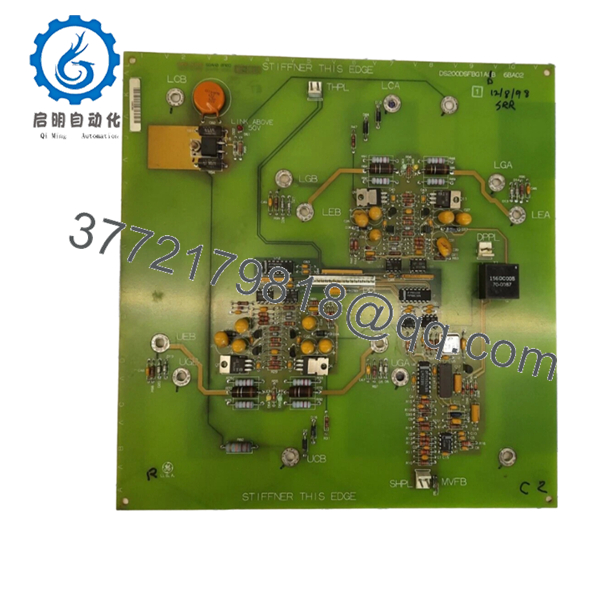
| Model Number | DS200DSFBG1A |
| Manufacturer | GE General Electric |
| Product Category | Drive Snubber Feedback Board |
| Platform | GE Mark V Drive System |
| PCB Type | Signal Processing / Feedback Interface |
| Mounting | Rack / Control Cabinet PCB Installation |
| Communication | Internal drive backplane interface |
| Operating Temperature | Typically 0 °C to 60 °C (verify OEM documentation) |
| ESD Sensitivity | High — ESD handling required |
| Application | Drive control and snubber feedback monitoring |
| Firmware | Hardware revision dependent |
| Product Status | Legacy / Obsolete |
| Condition Availability | New Surplus or Refurbished Tested |
4. Product Introduction
The GE DS200DSFBG1A is a drive snubber feedback board used within GE Mark V drive control systems. It processes and transfers snubber circuit feedback signals used by legacy industrial drive assemblies in turbine and process applications.
In field replacements of older GE systems, boards like the DS200DSFBG1A typically become failure points due to age, thermal cycling, and cabinet contamination. Plants often keep spare inventory because OEM production has ended and replacement lead times can become unpredictable.

- DS200DSFBG1A
5. Installation & Configuration Guide
Stage 1: Pre-Installation Preparation (Estimated Time: 10 minutes)
⚠️ Safety First: Notify operations of planned downtime. Place the system in a verified safe state. Lock out/tag out all incoming power. Wait 5 minutes minimum for capacitor discharge inside the drive cabinet.
Tools Required:
- ESD wrist strap
- PH1 screwdriver
- Digital multimeter (Fluke 115 recommended)
- Wire labels
- Smartphone for photos
- Flashlight for cabinet inspection
Data Backup
- Export available controller configuration files.
- Record drive fault history.
- Photograph all connector locations.
- Photograph cable routing and wire positions.
- Record any board revision labels.
⚠️ Legacy GE cabinets frequently contain undocumented field modifications. Never trust existing cabinet drawings alone.
Stage 2: Removing the Old Module (Estimated Time: 5–10 minutes)
Steps:
- Remove cabinet covers and access panels.
- Label and disconnect all attached connectors.
- Do not pull on cable bundles. Grip connectors only.
- Release board retaining hardware.
- Pull the board straight out.
- Inspect mating connectors and backplane pins.
⚠️ Note: Keep the old board nearby until startup completes successfully.
I’ve seen technicians throw failed boards into a box immediately. Two hours later they realize a jumper position was never documented.
Stage 3: Installing the New Module (Estimated Time: 5 minutes)
Steps:
- Attach ESD strap before touching the PCB.
- Verify DS200DSFBG1A revision exactly matches existing hardware.
- Configuration Clone (Crucial): Compare jumper settings and hardware options with photos.
- Insert board evenly into guide rails.
- Press firmly until fully seated.
- Reconnect wiring and connectors.
Self-Checklist:
- DIPs match
- Wiring secured
- Retention tabs locked
- Connector orientation verified
⚠️ This is the most common rookie mistake, but it happens constantly. Take a picture before you pull it. I can’t stress this enough.
Stage 4: Power-On & Testing (Estimated Time: 10 minutes)
Pre-Power Check
Use a multimeter to verify no short exists on the 24 V rail.
Power-On Sequence:
- Power rack and cabinet only.
- Observe startup LEDs.
- Verify no immediate faults.
- Connect engineering workstation.
- Review diagnostic screens.
- Perform dry-run I/O checks.
LED guidance:
- Green RUN: Normal startup
- Red ERR: Fault state
⚠️ Troubleshooting Note: If faults appear immediately after replacement, inspect firmware revision compatibility and board revision suffixes.
I’ve seen projects sit offline for two days because a board revision quietly changed and timing behavior shifted enough to trigger communication faults.
6. Frequently Asked Questions (FAQ)
Q1. Can I hot-swap this module?
No. Do not hot-swap the DS200DSFBG1A.
This board operates within legacy GE drive architecture that was not designed for live insertion. Pulling the board under power can damage the backplane or create transient failures that are difficult to diagnose. Kill power first.
Q2. Is DS200DSFBG1A obsolete, and is inventory genuinely new?
Yes. This is an obsolete GE part.
Current market inventory usually falls into two categories:
- New Original / New Surplus from unused warehouse stock
- Refurbished tested units removed from systems and requalified
Ask for date codes and inspection photos before purchase.
Q3. What is the direct replacement if this model is unavailable?
For GE legacy boards, replacement depends heavily on installed drive architecture and board revision.
DS200 series hardware sometimes has later revisions, but never assume suffix interchangeability. Verify:
- Hardware revision letter
- Connector layout
- Firmware dependencies
- OEM cross-reference documentation
Don’t swap by appearance.
Q4. Will I lose programming logic if I remove this board?
Typically no.
The DS200DSFBG1A functions as a feedback board rather than a controller CPU. Logic normally resides elsewhere within the control architecture. Still, always create backups before shutdown.
I’ve seen assumptions become expensive.
Q5. Why does pricing vary so much for this part?
Supply conditions.
OEM production ended years ago. Pricing now depends on:
- New surplus availability
- Repair history
- Test documentation included
- Warranty period
- Geographic inventory location
Two boards with the same part number can differ substantially in actual condition.
Q6. How do you test legacy GE boards before shipment?
Our standard inspection workflow follows this sequence:
Inbound Inspection & Traceability
- Verify source documentation
- Inspect serial labels
- Check for corrosion, rework marks, UV yellowing
- Verify accessories and revision labels
Live Functional Testing
- Bench tested using compatible GE hardware where available
- Power-on verification
- Communication checks
- Signal simulation
- Continuous run testing over 24 hours with thermal observation
Electrical Testing
- 500 V insulation resistance test (>10 MΩ)
- Ground continuity checks
- Hipot test if required
Firmware Verification
- Record hardware and firmware revisions
- Document jumper and switch settings
Final QC
- QC signoff
- Anti-static packaging
- Bubble protection and heavy-duty boxing
- QC date labeling
Test photos and videos are available upon request.
Q7. What installation mistake causes the most downtime?
❗DIP switches, jumpers, and undocumented settings.
I’ve watched experienced technicians replace a board in ten minutes and spend eight hours troubleshooting because one termination jumper stayed in factory default position.
Take pictures before removal. Keep these checks in mind and you’ll save yourself 90% of typical rework time.


