
 WhatsApp: +86 16626708626
 Email:
  Phone: +86 16626708626
Description
3. Key Technical Specifications
| Parameter | Value |
|---|---|
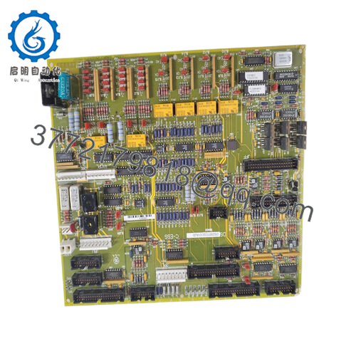
| Model | DS200DTBDG1ABB |
| Brand | GE (General Electric) |
| Series | Mark V Speedtronic |
| Product Type | Terminal Relay Board (Relay Driver / I/O Termination) |
| Logic Power Supply | 24V DC ±20% (from backplane or external) |
| Power Consumption | ≈5W (no load), higher with all relays energized |
| Relay Channels | 10 x SPDT (Form C) |
| Relay Contact Rating | 10A at 250V AC / 30V DC (resistive load) |
| Contact Material | Silver alloy (AgCdO) with arc suppression (RC snubber across each contact) |
| Input Signal Compatibility | NPN or PNP, 24V DC digital (jumper configurable) |
| Isolation Voltage | 2,500 Vrms (coil to contact) |
| Field Terminals | 2 x 10⁷-position pluggable terminal blocks (214 total) |
| Backplane Connectors | 3 x 34-pin, 4 x 30-pin |
| Status Indicators | 4-color LED array (power, coil status per channel, fault) |
| Operating Temp | -40°C to +85°C |
| Storage Temp | -40°C to +85°C |
| Humidity | 5% to 95% non-condensing |
| Dimensions | 11.25 x 3.0 inches (286 x 76 mm) |
| Mounting | Rack-mount (Mark V card cage) or M4 studs |
| MTBF | >200,000 hours (MIL-HDBK-217F, GB) |
| Coating | Conformal coated for harsh environments |
| GE Part Family | DS200 (Mark V) |
| Communication | ARCNET 2.5 Mbps (status reporting) |
4. Product Introduction
The GE DS200DTBDG1ABB is a terminal relay board for the Mark V Speedtronic turbine control system. This board translates low-voltage digital signals from the Mark V controller (24V DC logic) into high-power relay contacts capable of driving solenoids, contactors, motor starters, valve actuators, and alarm annunciators. It also terminates field wiring from sensors and limit switches back to the controller
The DTBD board integrates 10 SPDT relays (10A rating) and 214 field wiring terminals on a single 6U-height PCB. Each relay includes an RC snubber for arc suppression and is optically isolated from the logic side at 2,500 Vrms The board accepts both NPN and PNP input signals via configurable jumpers, eliminating the need for external interposing relays. Dual 107-position pluggable terminal blocks allow field wiring removal without unbolting wires — swap a failed board in under 2 minutes Onboard 4-color LEDs indicate power, relay coil status (green = energized, amber = overcurrent, red = hardware fault), and ARCNET communication health. If your Mark V turbine is failing to start, trip, or respond to commands, this board is likely the interface between the controller logic and the field devices.
5. Installation & Configuration Guide
Estimated time for replacement by a qualified technician: 20-30 minutes
Stage 1: Pre-Installation Preparation (10 minutes)
⚠️ Safety First: Notify operations of turbine shutdown. Lock out/tag out control power to the Mark V rack (24V DC logic supply and any external 120/240V AC or 125V DC power feeding relay contacts). Verify with a multimeter that all connected field circuits are de-energized. Wait 2 minutes for capacitors to discharge.
Tools Required:
- ESD wrist strap (grounded to earth)
- Small flathead screwdriver (3mm) for terminal blocks
- Multimeter with continuity and diode check
- Needle-nose pliers (for jumper adjustments)
- Smartphone for photos
- 24V DC power supply (optional, for bench test)
- Flashlight
Documentation (Critical):
- Take a high-resolution photo of the entire board, showing:
- All jumper positions (input configuration, NPN/PNP selection)
- Any DIP switch settings (if present on your specific revision)
- Wire colors and terminal numbers on both 107-position blocks
- Document which relay channel (K1-K10) controls which field device (e.g., K1 = Main Fuel Valve, K2 = Starter Motor).
- Note the field device voltage and current requirements (to verify the 10A contact rating is sufficient).
- If possible, record the configuration in the Mark V software (Control System Toolbox or legacy programming tool).
Stage 2: Removing the Old Board (5 minutes)
Step 1: Remove power to the Mark V rack. Measure voltage at the board’s power input terminals to confirm 0V DC.
Step 2: Loosen the two retaining screws at the top and bottom of the board’s front panel.
Step 3: Gently pull the board straight out of the card cage. Do not rock side to side — this bends backplane pins.
Step 4: Do not remove the field wiring from the terminal blocks. The DTBD board uses pluggable terminal blocks. Squeeze the locking tabs on each 107-position block and pull them straight off the board -1. The wires remain attached to the terminal blocks.
Step 5: Inspect the backplane connector for bent pins, corrosion, or debris. Use a flashlight.
Step 6: Place the old board on an ESD mat. Keep it for reference until the new board is running.
Stage 3: Installing the New Board (10 minutes)
Step 1 (ESD): Ground your wrist strap. Unpack the new DS200DTBDG1ABB on an ESD mat.
Step 2 (Verify Model): Confirm the label reads DS200DTBDG1ABB. Do not substitute DTBDG1ABC (adds analog outputs) or DTBDH1A (Mark VIe, different backplane) without engineering review -1.
Step 3 (Clone Configuration — Critical):
- Set all jumpers to match the photo of the old board. This includes input type (NPN vs PNP) and any channel-specific configurations.
- If your board has DIP switches, set them to match exactly.
Step 4: Insert the new board into the same card cage slot. Push evenly until the retaining screws align with the mounting holes.
Step 5: Tighten the top and bottom retaining screws to secure the board.
Step 6: Reinstall the two 107-position terminal blocks onto the new board. Press firmly until the locking tabs click into place.
Self-Checklist:
- Jumpers and DIP switches match old board
- Board fully seated and screws tightened
- Terminal blocks locked in place
- No wires pinched or bent
Stage 4: Power-On & Testing (5 minutes)
Pre-Power Check:
- Measure resistance between 24V+ and 24V- terminals on the board. Should be >10k ohms.
- For each relay output channel, measure resistance between common (C) and normally closed (NC), and between C and normally open (NO) with the board powered off. NC should be near 0 ohms; NO should be open.
Power-On Steps:
- Apply 24V DC control power to the Mark V rack.
- Observe the status LEDs on the DTBD board :
- Power LED (green): Must be steady on.
- ARCNET/Comm LED: Should blink to indicate communication with the main controller.
- Relay coil LEDs: Should match the commanded state from the controller (green = energized).
- Connect the Mark V maintenance terminal or operator interface.
- Input test (if digital inputs are wired to this board): Toggle each field input (limit switch, pressure switch, etc.) and verify the controller sees the state change.
- Output test (critical — coordinate with operations):
- Place the turbine in a safe state (e.g., maintenance mode, fuel off).
- From the controller, command each relay channel ON one at a time.
- Verify the field device responds (valve opens, contactor pulls in, lamp lights).
- Listen for each relay clicking — audible confirmation of coil operation.
- For inductive loads (solenoids, contactor coils), verify the RC snubber is installed across the contact. Without it, the relay contacts will weld closed within weeks
⚠️ Troubleshooting:
| Symptom | Likely Cause | Action |
|---|---|---|
| Power LED off | 24V DC missing or polarity reversed | Measure voltage at power terminals. Check backplane connection. |
| No communication with controller | ARCNET cable disconnected or board not recognized | Reseat board. Check ARCNET connections to the main controller. Verify board slot address matches configuration. |
| Relay coil LED on but field device does not operate | Relay contacts failed or wiring open | Measure continuity across relay contacts (C to NO) when energized. Check field wiring at the terminal block. |
| Relay chatters or buzzes | Coil voltage low or PWM control issue | Measure coil voltage (should be 24V DC nominal). Check controller output configuration. |
| LED shows amber (overcurrent) | Relay coil current exceeds spec or shorted coil | Replace board. Do not reset — investigate cause of overcurrent |
| LED shows red (hardware fault) | Relay driver transistor failed or internal bus fault | Replace board immediately |
| Field device operates intermittently | Loose terminal block connection or relay contact pitting | Retorque all terminal screws. Replace board if pitting is visible. |
| Multiple relays fail to operate | Backplane communication loss or power supply sag | Measure 24V DC under load (all relays energized). Replace power supply if voltage drops below 21V. |

- DS200DTBDG1ABB

6. Frequently Asked Questions (FAQ)
Q: Is the DS200DTBDG1ABB a controller or a CPU?
A: No. This is a terminal relay board (I/O termination and relay driver), not a processor. It does not execute control logic. It interfaces between the Mark V controller (e.g., DS200LDCCH1AKA) and field devices The controller sends 24V DC logic signals to this board; the board’s relays switch high-power loads.
Q: What is the difference between DTBDG1ABB and DTBDG1ABC?
A: The “ABB” suffix is the standard version with 10 relay outputs. The “ABC” variant adds 2 channels of 4-20 mA analog output for driving servo valves or proportional actuators -1. Do not substitute one for the other without verifying your application’s requirements — the ABC version may have different terminal assignments.
Q: Can I use this board with Mark VI or Mark VIe systems?
A: No. The DS200DTBDG1ABB is designed for the Mark V backplane and ARCNET communication protocol. Mark VI and Mark VIe use different termination boards (e.g., IS200DTBDH1A) with different connectors and communication protocols . Physically, the board may fit, but the pinout and backplane signals are incompatible. You will damage both boards.
Q: Why do my relay contacts keep welding closed?
A: You are switching an inductive load (solenoid, relay coil, contactor, motor starter) without adequate arc suppression. When the relay opens, the collapsing magnetic field generates a high-voltage spike that arcs across the contacts, welding them. Fix: The DTBD board includes an RC snubber (100Ω resistor + 0.1μF capacitor) across each contact by default . Verify the snubber is present and not damaged. For DC inductive loads, add a flyback diode across the load (cathode to V+, anode to V-). For AC loads, use a varistor (VDR) or larger RC snubber.
Q: Can I hot-swap the DTBD board while the turbine is running?
A: Absolutely not. The terminal blocks are pluggable, but the backplane carries live 24V DC and ARCNET communication signals. Removing the board while powered can:
- Arc the backplane pins (causing permanent damage)
- Trigger false trips or alarms in the controller
- Leave field devices in an indeterminate state (relay contacts open when board removed)
Procedure: Shut down the turbine, lock out control power, wait 30 seconds, then swap.
Q: How do I wire a 120V AC load to the relay contacts?
A: The relay contacts are rated for 10A at 250V AC -1. Wiring is straightforward:
- Connect the hot leg (L1) of the 120V AC supply to the relay Common (C) terminal.
- Connect the load (e.g., contactor coil) between the Normally Open (NO) terminal and Neutral (N).
- When the relay energizes, the contact closes and powers the load.
⚠️ Safety: Ensure the 120V AC circuit is de-energized and locked out before wiring. Keep 120V AC wiring separate from 24V DC logic wiring (use different conduits or maintain 30cm separation).
Q: What is the ARCNET connection used for?
A: The DTBD board reports status back to the Mark V controller over ARCNET (2.5 Mbps) This includes:
- Relay coil health (energized vs fault)
- Contact weld detection (if equipped on your board revision)
- Board temperature and power status
The controller uses this data for diagnostics and alarm generation. If the ARCNET LED is off or not blinking, the board is not communicating with the main controller.
Q: How do I bench test the DTBD board without a Mark V rack?
A: You need a 24V DC power supply (2A minimum) and a multimeter. Procedure:
- Connect 24V DC to the power terminals (refer to the pinout diagram).
- The Power LED should illuminate.
- For each relay channel (K1-K10), apply 24V DC to the coil input pin (consult the jumper configuration for which pin is the coil+).
- Listen for the relay click. Measure continuity between Common (C) and Normally Open (NO) — should be near 0 ohms.
- Remove the 24V DC from the coil. Measure continuity between C and Normally Closed (NC) — should be near 0 ohms.
This test confirms relay operation but does not verify ARCNET communication.
Q: What’s your testing process for this board?
A: We test every DS200DTBDG1ABB on a live Mark V test rack with a known-good controller. Test sequence:
- Visual inspection (conformal coating integrity, terminal block condition, no burnt components)
- Power-on test (24V DC, LED sequence, current draw)
- ARCNET communication test (verify board is detected by controller)
- Relay test: All 10 channels, cycle 100 times at 1 Hz, verify contact resistance <0.5Ω
- Inductive load test: Switch a 24V DC relay coil (without snubber) 10 times to verify arc suppression works
- Isolation test: 2,500 Vrms between coil and contacts for 5 seconds
- Thermal test: All 10 relays energized simultaneously, 24 hours at 50°C ambient, monitor temperature rise
- Input test (if equipped with digital inputs): Toggle each input, verify controller sees state change
Test report with relay contact resistance measurements and thermal images available upon request.
Q: What’s the warranty on this obsolete board?
A: 1-year replacement warranty. Covers failure under normal operating conditions (-40°C to +85°C, 24V DC ±20%). Does NOT cover damage from:
- Welded relay contacts due to missing or failed snubbers (inductive loads)
- Overvoltage on inputs (>30V DC)
- Water ingress or corrosive atmosphere (despite conformal coating)
- Physical damage to terminal blocks or connectors
- ESD or lightning strikes
We cross-ship replacements within 24 hours for confirmed defects. We also offer a 30-day compatibility guarantee — if the board does not work in your specific Mark V rack (e.g., wrong firmware or backplane incompatibility), return it for full credit.


