
 WhatsApp: +86 16626708626
 Email:
  Phone: +86 16626708626
Description
3. Key Technical Specifications
| Parameter | Value |
|---|---|
| Manufacturer | GE General Electric |
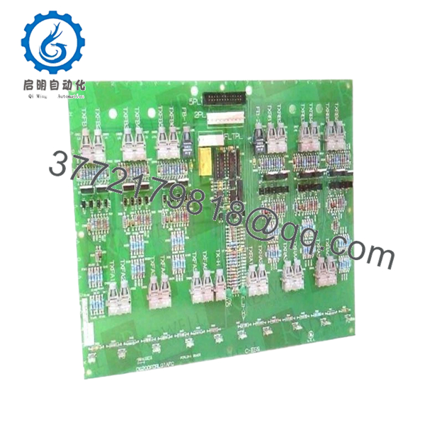
| Model Number | DS200FCRLG1A |
| Product Type | Firing Circuit Control Board |
| Series | Mark V Speedtronic / Drive Control |
| Primary Function | SCR firing and excitation regulation |
| Application | Turbine generator excitation systems |
| System Compatibility | GE Mark V control systems |
| Connector Count | 27 bayonet-type connectors |
| Additional Interfaces | 1 × 34-pin connector, 1 × 9-pin connector |
| Typical Power Requirement | 24 V DC or cabinet control supply |
| Control Method | Firing pulse generation and regulation control |
| Mounting Style | Rack-mounted PCB |
| Operating Temperature | 0 °C to 60 °C typical cabinet rating |
| Humidity Rating | 5% to 95% non-condensing |
| Approximate Weight | 0.9 kg (2.0 lb) |
| PCB Protection | Industrial conformal-coated assembly |
| Condition | New Original / New Surplus |
| Warranty | 12 Months |
4. Product Introduction
The GE DS200FCRLG1A is a firing circuit control board used in GE Mark V turbine and excitation control systems. The board manages SCR firing control, excitation regulation, and associated signal processing for generator control applications in gas and steam turbine environments.
In field retrofits and outage recovery work, this board is commonly used to maintain legacy Mark V installations without migrating to newer control architectures. Engineers typically retain the original DS200FCRLG1A revision to avoid excitation instability, communication faults, or parameter mismatches introduced by unsupported substitutions.
5. Installation & Configuration Guide
Stage 1: Pre-Installation Preparation (Estimated Time: 10 Minutes)
⚠️ Safety First
- Notify operations and obtain outage approval.
- Verify generator excitation systems are offline.
- Lock out and tag out all cabinet power sources.
- Wait at least 5 minutes for DC bus discharge.
⚠️ Excitation cabinets can retain dangerous stored energy even after shutdown. Verify with a meter before touching the rack.
Tools Required
- ESD wrist strap
- PH1 screwdriver
- Fluke 115 multimeter
- Insulated needle-nose pliers
- Wire labels
- Smartphone for configuration photos
Data Backup
- Export current excitation and regulator settings.
- Photograph all connectors and cable routing.
- Record jumper and connector positions.
- Document cabinet slot location and associated wiring.
❗ Take photos before disconnecting anything. This sounds basic, but during a 2 AM outage, nobody remembers which connector went where.
Stage 2: Removing the Old Module (Estimated Time: 5–10 Minutes)
- Open the cabinet front panel.
- Label all wiring and signal connectors.
- Disconnect bayonet connectors carefully.
- Remove retaining screws or extraction clips.
- Pull the board straight out without twisting.
⚠️ Do not rock the board side to side. Mark V backplane connectors are old, and bent pins create intermittent faults that waste hours.
- Inspect:
- Connector pins
- PCB edge contacts
- Dust accumulation
- Heat damage
- Oxidation around terminals
Important Field Reminder
Keep the original module nearby until startup is complete. I’ve seen technicians throw the old board into scrap bins too early, only to realize later they needed jumper references from the original hardware.
Stage 3: Installing the New Module (Estimated Time: 10 Minutes)
- Wear a grounded ESD strap.
- Verify the exact model number: DS200FCRLG1A.
- Confirm connector layout and revision markings match the original board.
Configuration Clone (Crucial)
- Replicate all jumper and connector configurations exactly.
- Verify excitation loop wiring orientation.
- Check grounding and shielding termination.
❗ This is the most common rookie mistake in excitation systems. Ground the shield at both ends and you’ll chase unstable firing pulses for hours.
- Insert the board evenly into the rack guides.
- Push firmly until fully seated.
- Reinstall retaining hardware.
- Reconnect all cables carefully.
Self-Checklist
- Model verified
- Jumpers replicated
- Connectors fully seated
- Shielding grounded correctly
- Retaining hardware tightened
Stage 4: Power-On & Testing (Estimated Time: 15 Minutes)
Pre-Power Check
- Verify no shorts on the 24 V DC rail.
- Check cabinet grounding continuity.
- Inspect all firing and excitation wiring.
⚠️ CT secondary circuits must remain properly shorted during maintenance. Open-CT conditions can create dangerous voltage spikes.
Power-On Steps
- Energize the control rack only.
- Observe startup LEDs and diagnostics.
- Verify communication with the Mark V controller.
- Connect engineering software and verify board recognition.
- Confirm excitation feedback signals.
- Perform dry-run excitation and I/O testing before returning the turbine to service.
SOP Testing Performed Before Shipment
Our QC workflow includes:
- Inbound Inspection & Traceability
- OEM label verification
- Serial number inspection
- Corrosion and rework inspection
- Connector integrity check
- Live Functional Testing
- Tested on a genuine GE Mark V rack
- Communication handshake verification
- Simulated firing control tests
- Continuous thermal run exceeding 24 hours
- Electrical Parameter Testing
- 500 V insulation resistance test (>10 MΩ)
- Ground continuity verification
- Power rail stability testing
- Firmware & Revision Documentation
- Revision identification recorded
- Connector and jumper photos archived
- Final QC & Packaging
- ESD-safe anti-static packaging
- Heavy-duty export carton
- QC sign-off with inspection date
Test videos and inspection photos are available upon request.
⚠️ Troubleshooting Notes
- Solid fault LEDs usually indicate connector seating or excitation loop faults.
- Intermittent communication alarms often trace back to grounding or shield termination problems.
- If firing instability appears immediately after startup, verify jumper replication before replacing additional boards.

- DS200FCRLG1A
6. Frequently Asked Questions (FAQ)
Q1: Can I hot-swap the DS200FCRLG1A under power?
No. Do not hot-swap this board.
The DS200FCRLG1A interacts directly with excitation and firing control circuitry. Pulling it live can damage the backplane or trigger unstable SCR firing conditions. Shut the cabinet down completely first.
Q2: Is the DS200FCRLG1A obsolete?
Yes. The Mark V platform is legacy equipment.
GE no longer manufactures these boards through standard OEM production channels. Most available inventory today comes from surplus stock, plant spares, or professionally tested refurbished inventory.
Q3: Is this genuinely new or refurbished stock?
This listing is for New Original / New Surplus inventory unless specifically labeled otherwise.
That means:
- No previous field installation
- Industrial spare inventory storage
- OEM-manufactured hardware
Because these boards are older, outer packaging may show storage wear. We inspect every board for oxidation, damaged traces, and connector deterioration before shipment.
Q4: Will replacing this board erase my turbine logic?
Normally no. The DS200FCRLG1A primarily handles firing and regulation functions rather than storing primary turbine sequencing logic.
Still, always back up the system first. I’ve seen sites lose undocumented parameter adjustments because nobody exported the excitation settings beforehand.
Q5: What is the biggest installation mistake with this board?
Firmware and configuration mismatch.
I’ve seen engineers replace an older board revision with a newer one, then spend two days troubleshooting “communication timeout” alarms. The hardware fit physically, but the excitation interface behavior changed slightly between revisions.
Document everything before removal.
Q6: Why are Mark V excitation boards expensive?
Because outages are expensive.
If a turbine is offline waiting for a firing control board, the hardware cost becomes secondary compared to lost generation revenue. Plants often pay premium prices for verified spare inventory that can ship immediately.
Q7: What precautions matter most during installation?
Three things:
- Correct jumper replication
- Proper CT handling
- ESD protection
❗ I once watched an engineer replace an excitation board without using an ESD strap during winter conditions. The board powered up briefly, then failed permanently. The outage extended another full shift while another spare was sourced.
Keep these checks in mind and you’ll save yourself 90% of typical rework time.


