
 WhatsApp: +86 16626708626
 Email:
  Phone: +86 16626708626
Description
3. Key Technical Specifications
| Parameter | Value |
|---|---|
| Model Number | DS200FGPAG1A |
| Manufacturer | GE Energy |
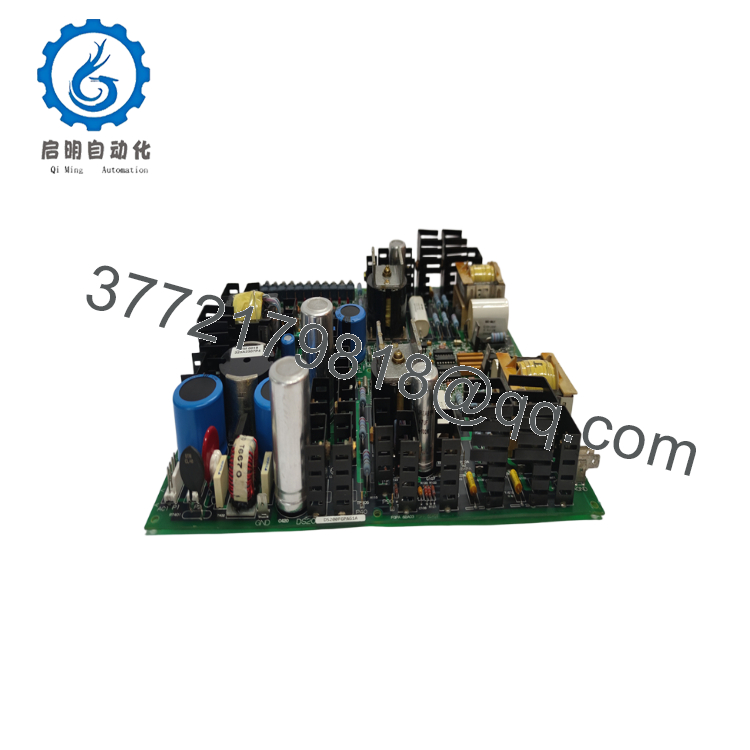
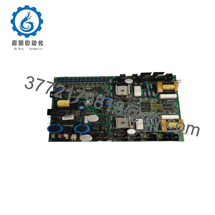
| Product Type | Gate Pulse Amplifier Board |
| Series | LS2100 Static Starter (LCI) |
| Primary Function | SCR Gate Drive & Status Monitoring |
| Gate Driver Circuits | 2 |
| Fiber Optic Ports | 15 (1 Transmitter, 14 Receivers) |
| Test Points | 30 Total (9 Gate A, 9 Gate B, 12 Cell Status) |
| Input Control Voltage | 120 VRMS ±20% |
| Maximum Power Consumption | Approximately 350 VA |
| Converter Supply Compatibility | 2080 VAC or 3300 VAC Twelve-Pulse Converter |
| Compatibility | Not backward compatible between certain revisions |
| Operating Application | GE Load Commutated Inverter (LCI) Static Starter Systems |
4. Product Introduction
The GE DS200FGPAG1A is a Gate Pulse Amplifier Board designed for GE LS2100 Load Commutated Inverter (LCI) static starter systems. It provides gate drive signals for one SCR bridge phase while continuously monitoring SCR health and converting AC control power into regulated DC operating voltages.
Engineers commonly select this board because it combines gate drive, SCR status monitoring, and fiber-optic communication on a single assembly. Proper revision selection is important because several hardware revisions are not backward compatible. Always verify the existing board revision before ordering.
5. Installation & Configuration Guide
Stage 1 – Pre-Installation Preparation (10 minutes)
⚠️ Safety First
- Notify operations of scheduled downtime.
- Shut down the LCI system following plant procedures.
- Lock out and tag out all incoming power.
- Wait at least 5 minutes for DC bus capacitors to discharge.
- Verify zero voltage using a calibrated multimeter.
Tools Required
- ESD wrist strap
- PH1 screwdriver
- Digital multimeter (Fluke 115 or equivalent)
- Wire labels
- Smartphone for documentation
Data Backup
- Save all drive configuration files.
- Record firmware revision.
- Photograph:
- Fiber-optic connections
- Wiring terminals
- Board location
- Jumper or hardware settings
Stage 2 – Removing the Existing Board (5 minutes)
- Remove cabinet covers.
- Label every connector before removal.
- Disconnect fiber-optic cables carefully.
- Remove mounting hardware.
- Pull the board straight out without twisting.
- Inspect connectors and backplane for bent pins or contamination.
⚠️ Keep the original board until commissioning is complete.
Stage 3 – Installing the New Board (10 minutes)
- Wear an ESD strap before handling the board.
- Verify the complete part number and hardware revision.
- Compare jumpers and configuration with the original assembly.
- Install the board evenly into its mounting position.
- Tighten mounting hardware.
- Reconnect all fiber-optic and electrical connectors.
Self-Checklist
- ✔ Model number verified
- ✔ Hardware revision verified
- ✔ Connectors fully seated
- ✔ Fiber optics installed correctly
- ✔ Mounting hardware secured
Stage 4 – Power-On & Functional Testing (10–15 minutes)
Pre-Power Checks
- Measure the 24 V control supply.
- Verify no short circuit exists.
- Confirm all connectors are fully seated.
Startup Procedure
- Energize the control rack.
- Observe LED indications.
- Confirm normal boot sequence.
- Connect GE maintenance software if applicable.
- Verify board communication.
- Confirm SCR status signals.
- Perform a dry-run before reconnecting the driven equipment.
⚠️ Troubleshooting
- Solid ERR LED: Check hardware revision and firmware compatibility.
- No communication: Verify fiber-optic routing and connector orientation.
- SCR faults: Inspect gate driver outputs and control voltage.
- Intermittent alarms: Clean fiber connectors and inspect optical cables.

- DS200FGPAG1A
- DS200FGPAG1A
6. Frequently Asked Questions (FAQ)
Q1. Can I hot-swap the DS200FGPAG1A?
No. This board is part of the SCR gate drive system. Removing it while energized can damage the control electronics or SCR bridge. Always isolate power before replacement.
Q2. Is the DS200FGPAG1A obsolete?
Yes. It is a legacy GE LS2100 component. New surplus inventory is limited, while professionally tested refurbished units are generally easier to source.
Q3. Will replacing this board erase my control logic?
No. The application logic resides elsewhere in the control system. However, always back up configuration files and document existing settings before maintenance.
Q4. Why must I verify the board revision?
GE released several hardware revisions, and some are not backward compatible. Installing the wrong revision can result in communication faults or startup failures. Always compare the complete part number and revision suffix before installation.
Q5. What are the main functions of this board?
The DS200FGPAG1A performs three primary tasks:
- Provides SCR gate drive signals
- Monitors SCR operating status
- Converts AC control power to regulated DC supplies for gate circuitry
Q6. Why is New Surplus inventory often less expensive than OEM pricing?
Many New Surplus units come from unused project inventory, plant closures, or excess OEM stock. They are genuine industrial components but are no longer manufactured, allowing distributors to offer them below historical OEM list prices.
Q7. What should I inspect before energizing the system?
An experienced commissioning engineer should verify:
- Correct hardware revision
- Fiber-optic cable routing
- Secure electrical connections
- Control power voltage
- Clean board connectors
- SCR bridge status
- Cabinet grounding
- ESD handling throughout installation
These checks eliminate most commissioning issues and substantially reduce unnecessary troubleshooting time.



