
 WhatsApp: +86 16626708626
 Email:
  Phone: +86 16626708626
Description
3. Key Technical Specifications
| Parameter | Value |
|---|---|
| Product Type | Gate Driver Power Supply Board |
| Series | GE Mark V Speedtronic |
| Output Power | 600–700 W |
| Input Voltage (AC) | 80–132 V AC |
| Input Voltage (DC) | 105–140 V DC |
| Output Features | 120 V DC supply; 50 V AC transformer |
| Inverter Frequency | ~27 kHz |
| Protection Circuits | Overcurrent, overvoltage, undervoltage |
| Isolation | Fully isolated inputs |
| Indicators | 4 LEDs + 2 neon indicators |
| Operating Temperature | −20°C to +50°C |
| Weight | ~0.9–1.0 kg |
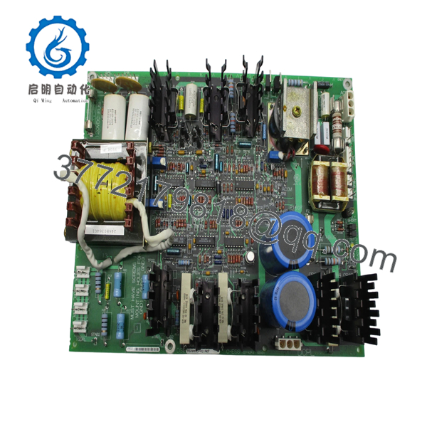
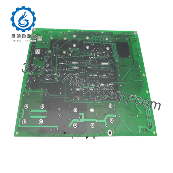
4. Product Introduction
The GE DS200GDPAG1A is a gate driver power supply board used in the Mark V Speedtronic turbine control system. It provides regulated power to gate driver circuits in excitation and drive systems, supporting both AC and DC input sources.
In field installations, this board is critical for stable operation of SCR/IGBT gating circuits. It integrates rectification, filtering, regulation, and a 27 kHz inverter on a single PCB, ensuring consistent voltage delivery under fluctuating plant conditions.
5. Installation & Configuration Guide
Stage 1: Pre-Installation Preparation (Estimated 10–15 minutes)
- ⚠️ Safety First: Shut down turbine/excitation system, apply lockout/tagout, wait at least 5 minutes for DC bus discharge.
- Tools Required: ESD strap, PH1 screwdriver, Fluke 115 multimeter, labeling tags, smartphone.
- Data Backup:
- Record system configuration from Mark V interface.
- Photograph board position and cable routing.
- Label all connectors before removal.
Stage 2: Removing the Old Module (Estimated 5–10 minutes)
- Open control cabinet and locate GDPA board.
- Disconnect all plugs and wiring harnesses carefully.
- Release mounting hardware or card guides.
- Pull board straight out — avoid stressing connectors.
- Inspect connectors for heat damage or carbon tracking.
- ⚠️ Note: Keep the old board for voltage reference and wiring verification.
Stage 3: Installing the New Module (Estimated 10 minutes)
- Use proper ESD grounding before handling.
- Verify exact model: DS200GDPAG1A (Revision A).
- Insert board evenly into guides.
- Secure mounting hardware.
- Reconnect cables exactly as labeled.
- Self-Checklist:
- Connectors fully seated
- No bent pins
- Board secured
Stage 4: Power-On & Testing (Estimated 10–15 minutes)
- Pre-Power Check: Verify no shorts on input rails.
- Power-On Steps:
- Energize control cabinet.
- Observe LED/neon indicators.
- Measure output voltages (120 V DC / 50 V AC).
- Confirm gate driver circuits receive stable supply.
- Monitor for abnormal heat or noise.
- ⚠️ Troubleshooting Note:
- No output → check AC/DC input range and fusing.
- Voltage instability → suspect regulator or external load issue.
6. Frequently Asked Questions (FAQ)
Q1: Can this board accept both AC and DC input?
Yes. It supports dual input modes: 80–132 V AC or 105–140 V DC. Just make sure the input is impedance-limited and properly fused.
Q2: Is this module obsolete?
Yes. Mark V is a legacy platform. These boards are no longer manufactured and are sourced from surplus or refurbished inventory.
Q3: What happens if input voltage is out of range?
You’ll trip protection circuits or damage internal components. I’ve seen overvoltage events take out both the GDPA and downstream gate boards.
Q4: Is this interchangeable with DS200GDPAG1 (non-A revision)?
Not always. The “A” revision includes functional updates. Always match the full part number unless verified otherwise.
Q5: What’s the most common failure mode?
Electrolytic capacitor degradation and inverter failure. After years of operation, ripple increases and causes unstable gate signals.
Q6: Why is this board critical to turbine operation?
Because it feeds the gate driver circuits. If this board fails, SCR/IGBT firing becomes unstable or stops entirely—effectively disabling the drive or excitation system.

- DS200GDPAG1A
SOP Quality Transparency
1. Inbound Inspection & Traceability
- Verified against GE Mark V part numbering and documentation.
- Serial and revision inspected.
- Visual inspection: no capacitor bulging, no PCB discoloration, intact coating.
- Connector pins inspected under magnification.
2. Live Functional Testing
- Tested on a GE Mark V simulation rack with load bank.
- Verified AC/DC input switching.
- Output voltage stability tested under load.
- Continuous runtime: 24-hour load test.
- Inverter operation (~27 kHz) verified via oscilloscope.
- Test report available upon request.
3. Electrical Parameter Testing
- Insulation resistance >10 MΩ @ 500 V Megger.
- Ground continuity verified.
- Output ripple measured (<100 mV typical).
4. Firmware & Configuration Verification
- No firmware dependency (hardware power board).
- Revision and hardware configuration recorded.
5. Final QC & Packaging
- QC inspection sign-off with traceable report.
- Anti-static ESD packaging.
- Foam-protected industrial carton.
- QC Passed label with date.
Technical Pitfall & Survival Guide
❗ 1. Input Voltage Misconfiguration
I’ve seen engineers feed 230 V AC directly—this board is not designed for that.
Avoidance: Verify input range (80–132 V AC or 105–140 V DC) before energizing.
❗ 2. Ignoring Load Conditions
This board supplies up to ~700 W. If downstream circuits are shorted, it will trip or fail.
Avoidance: Check downstream gate circuits before installing a new board.
❗ 3. Revision Confusion (GDPAG1 vs GDPAG1A)
Looks identical, but behavior can differ.
Avoidance: Match exact suffix or confirm compatibility.
❗ 4. Poor Cooling / Cabinet Heat
These boards run warm due to inverter operation.
Real case: Failed within weeks because cabinet fans were clogged.
Avoidance: Verify airflow and cabinet temperature.
❗ 5. ESD Damage During Handling
Power boards are less sensitive than logic boards—but still vulnerable.
Avoidance: Always use grounding. One static hit can damage regulator circuits.


