
 WhatsApp: +86 16626708626
 Email:
  Phone: +86 16626708626
Description
3. Key Technical Specifications
| Parameter | Value |
|---|---|
| Manufacturer | GE / General Electric |
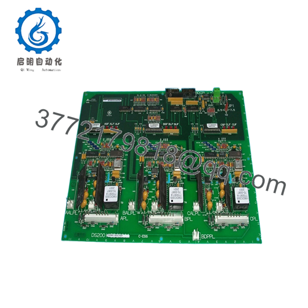
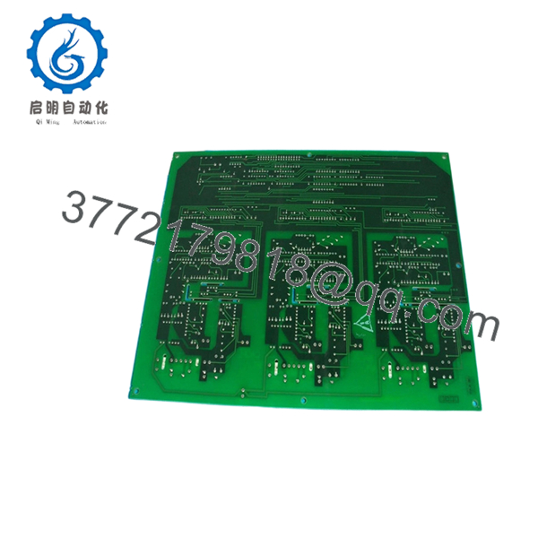
| Model Number | DS200IIBDG1AGA |
| Product Series | Speedtronic Mark V |
| Board Function | IGBT Gate Driver Board |
| Application | Turbine Control Systems |
| PCB Coating | Standard Industrial Coating |
| Connector Types | 34-pin ribbon connector, 8-pin signal connectors |
| Status Indicators | 9 onboard red diagnostic LEDs |
| Mounting Method | Cabinet-mounted PCB |
| Operating Environment | Industrial control cabinet installation |
| Typical System Use | GE Mark V gas/steam turbine drives |
| Approx. Weight | 0.8 kg |
| Country of Origin | United States |
| Firmware Dependency | Verify compatibility with installed Mark V revision |
| ESD Protection Requirement | Mandatory grounded handling procedures |
Technical details compiled from multiple industrial surplus references and Mark V field documentation. Verify final compatibility against the OEM maintenance manual before installation.
4. Product Introduction
The GE DS200IIBDG1AGA is an IGBT Gate Driver Board used in the Speedtronic Mark V turbine control platform. It interfaces gate drive signals, status monitoring, and control feedback within GE gas and steam turbine drive systems.
In field deployments of Mark V cabinets, this board is commonly installed in AC2000I drive sections where stable IGBT switching and signal isolation matter more than raw processing power. Engineers still source this model because many legacy turbine systems remain operational worldwide, and a direct replacement avoids a costly controls migration project.

- DS200IIBDG1AGA
- DS200IIBDG1AGA
5. Installation & Configuration Guide
Stage 1: Pre-Installation Preparation (Estimated Time: 10 Minutes)
⚠️ Safety First
- Notify operations and obtain shutdown approval.
- Place the turbine or drive system in a verified safe state.
- Lock out/tag out all incoming cabinet power.
- Wait at least 5 minutes for DC bus capacitors to discharge fully.
Tools Required
- Grounded ESD wrist strap
- PH1 screwdriver
- Fluke 115 multimeter or equivalent
- Wire labels
- Smartphone for reference photos
- Flashlight for cabinet inspection
Data Backup
- Export current controller configuration and drive parameters.
- Record cabinet slot location.
- Photograph:
- Ribbon cable orientation
- Connector positions
- DIP switch and jumper settings
- Grounding straps
- Document any field modifications.
⚠️ I’ve seen technicians assume “all Mark V boards are identical.” They are not. Minor revision differences can create startup faults that waste an entire shift.
Stage 2: Removing the Old Module (Estimated Time: 5–10 Minutes)
- Remove the cabinet front bezel or protective cover.
- Label every cable before disconnecting it.
- Disconnect ribbon cables carefully. Do not pull by the cable body.
- Remove retaining screws securing the board.
- Pull the board straight outward to avoid damaging backplane connectors.
- Inspect:
- Bent pins
- Carbon tracking
- Dust buildup
- Heat discoloration near power components
⚠️ Important: Keep the original board beside the cabinet until the replacement passes full runtime testing.
This sounds obvious, but I’ve watched maintenance teams throw the old board into scrap bins too early. Then the replacement fails firmware validation and nobody remembers the original jumper layout.
Stage 3: Installing the New Module (Estimated Time: 10 Minutes)
- Wear the grounded ESD strap before touching the PCB.
- Verify the replacement model exactly matches:
- DS200IIBDG1AGA
- Compare all jumpers and switch positions with the original board photos.
Configuration Clone (Crucial)
- Match every jumper position exactly.
- Verify node addressing.
- Verify any termination resistor settings.
⚠️ This is the most common rookie mistake, but experienced engineers get burned by it too. Take pictures before removal. I can’t stress this enough.
- Insert the board evenly into the mounting position.
- Tighten retaining screws evenly.
- Reconnect ribbon and signal cables carefully.
Self-Checklist
- Model numbers match
- Jumpers duplicated correctly
- Ribbon cables fully seated
- Ground connections secured
- Mounting screws tightened
- No loose hardware inside cabinet
Stage 4: Power-On & Testing (Estimated Time: 15 Minutes)
Pre-Power Check
- Use a multimeter to verify no short exists on the 24 V rail.
- Confirm cabinet grounding continuity.
Power-On Sequence
- Energize the rack only.
- Observe onboard LEDs.
- Green/RUN behavior normal
- Solid red LEDs indicate fault conditions
- Connect engineering workstation software.
- Verify:
- Board recognition
- Firmware compatibility
- Communication status
- Restore saved configuration if required.
- Perform dry-run I/O testing before enabling field outputs.
Communication Verification
- Confirm proper handshake with associated Mark V controllers.
- Check ribbon cable communication integrity.
- Verify no watchdog or timeout alarms appear.
⚠️ Troubleshooting Note
If the board powers up with communication faults:
- First suspect firmware revision mismatch.
- Second suspect incorrect jumper settings.
- Third suspect ribbon cable orientation.
I’ve seen a plant lose almost two days because a replacement board shipped with a newer firmware branch than the installed Mark V core. The hardware was fine. The protocol timing changed slightly and the controller rejected the board during initialization.
Technical Pitfall & Survival Guide
❗ Firmware Revision Mismatch
A newer board revision may not communicate correctly with older Mark V firmware.
Avoidance:
Document the existing firmware revision before removal. Request matching firmware ranges from the supplier when possible.
❗ DIP Switch / Jumper Errors
Factory defaults rarely match the running plant configuration.
Avoidance:
Mirror every jumper exactly from the original board.
One wrong termination setting can create intermittent communication faults that only appear under load.
❗ Ribbon Cable Orientation Mistakes
The 34-pin ribbon connector must align exactly.
Avoidance:
Mark cable orientation before disconnecting.
I once watched a startup team reverse a ribbon cable during a midnight outage. The board survived. The adjacent interface board did not.
❗ Power Supply Capacity
Legacy Mark V cabinets often run close to power supply limits.
Avoidance:
Verify total cabinet load and maintain at least 20% power margin.
❗ Electrostatic Discharge (ESD)
These boards are not forgiving.
Avoidance:
Always use grounded handling procedures and ESD mats.
I’ve personally seen an engineer handle a spare board in dry winter air without grounding. The board failed immediately on startup. Expensive lesson.
Keep these checks in mind and you’ll save yourself 90% of typical rework time.
6. Frequently Asked Questions (FAQ)
Q1: Can I hot-swap the GE DS200IIBDG1AGA under power?
No. Do not hot-swap this board.
The Mark V platform was not designed for casual live replacement of IGBT interface boards. Pulling the board under power risks damaging the backplane, corrupting communication, or tripping the turbine control system. Shut the cabinet down properly first.
Q2: Is DS200IIBDG1AGA obsolete?
Yes. This is an obsolete GE Mark V component.
Most available inventory today comes from:
- New surplus stock
- Decommissioned plant spares
- Professionally tested refurbished inventory
True factory-sealed inventory still exists, but quantities are limited globally.
Q3: Is this genuinely new or refurbished?
That depends on the specific inventory batch.
Always request:
- High-resolution board photos
- Serial labels
- Test reports
- Packaging photos
A trustworthy supplier should clearly state:
- New Original
- New Surplus
- Refurbished (tested)
If the seller avoids the question, assume refurbished.
Q4: Will I lose my logic or turbine configuration when replacing this board?
Normally no.
The DS200IIBDG1AGA itself does not typically store the primary turbine application logic. That logic usually resides in the Mark V controller processors.
However, jumper settings and hardware configuration still matter. Document everything before removal.
Q5: What should I verify before ordering a replacement?
At minimum:
- Exact suffix: DS200IIBDG1AGA
- Existing firmware revision
- Cabinet type
- Connector compatibility
- PCB coating style
- Jumper configuration
Even within Mark V systems, similar-looking boards may not be interchangeable.
Q6: Why are surplus market prices lower than OEM pricing?
Because most OEMs no longer manufacture these boards.
The secondary market prices inventory based on:
- Remaining stock
- Test condition
- Lead time
- Regional demand
A tested surplus board can cost far less than a full controls migration project, which is why many plants continue supporting Mark V systems instead of upgrading immediately.
Q7: What quality checks should a supplier perform before shipment?
Minimum acceptable checks should include:
- Visual PCB inspection
- Serial number traceability
- LED startup verification
- Connector integrity inspection
- 24-hour powered runtime testing
- Insulation resistance testing (>10 MΩ preferred)
- ESD-safe packaging
We strongly recommend requesting:
- Test videos
- QC photos
- Firmware documentation
- Packing photos before shipment
A serious automation supplier should have no issue providing them.


