
 WhatsApp: +86 16626708626
 Email:
  Phone: +86 16626708626
Description
3. Key Technical Specifications
| Parameter | Value |
|---|---|
| Manufacturer | General Electric (GE) |
| Model Number | DS200IMCPG1CBA |
| Functional Acronym | IMCP |
| Product Type | IGBT Power Supply Interface Board |
| Series | Mark V DS200 Speedtronic |
| Application | Turbine and Drive Control Systems |
| Primary Function | IGBT power supply management |
| Compatible System | GE Mark V Turbine Control |
| Interface Connection | 1PL connection to DS200SDCC board |
| Diagnostic Indicators | 2 × Green status LEDs |
| Ribbon Connectors | 34-pin and 40-pin ribbon connectors |
| PCB Coating | Normal protective coating |
| Functional Revision 1 | C |
| Functional Revision 2 | B |
| Artwork Revision | A |
| Mounting Method | Rack/cabinet mounted |
| Protection Features | Multiple onboard fuses and suppression circuits |
| Operating Environment | Industrial control cabinet installation |
| Approximate Weight | 1 lb (0.45 kg) |
| Condition Options | New Original, New Surplus, Refurbished (tested) |
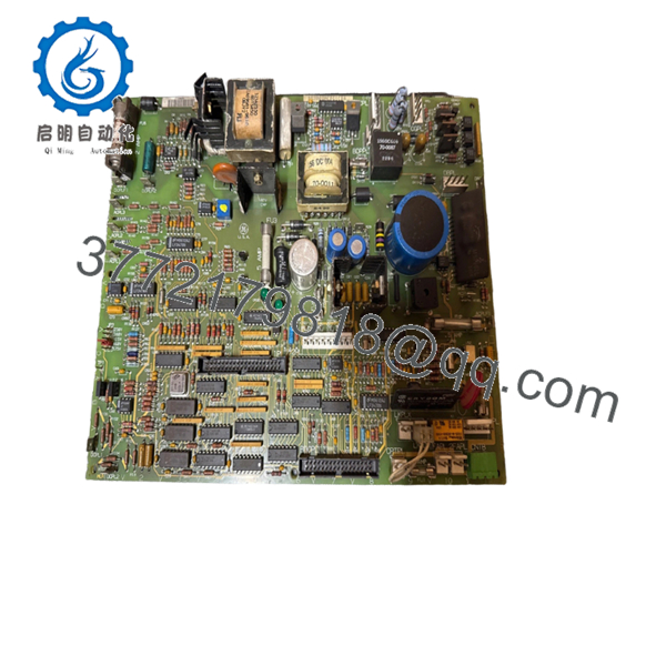
The DS200IMCPG1CBA is an IGBT Power Supply Interface Board used in GE Mark V Speedtronic systems for gas, steam, and industrial drive applications. It interfaces with the DS200SDCC Drive Control Board through the 1PL connector and manages regulated power distribution to associated drive circuitry.
4. Product Introduction
The GE DS200IMCPG1CBA is a Power Supply Interface Board designed for the Mark V Speedtronic control platform. It operates inside turbine and industrial drive systems where regulated IGBT power management and stable communication with the SDCC control board are required.
In field service work, this board commonly appears in legacy GE drive cabinets where maintaining hardware compatibility is more practical than performing a complete control retrofit. Engineers typically select matching revision levels carefully because Mark V boards are sensitive to revision and firmware inconsistencies between interconnected assemblies.

- DS200IMCPG1CBA
5. Installation & Configuration Guide
Stage 1: Pre-Installation Preparation (Estimated Time: 10 Minutes)
⚠️ Safety First
- Notify operations before shutting down the drive or turbine system.
- Bring the controlled equipment to a verified safe state.
- Apply lock out/tag out procedures to all incoming power sources.
- Wait at least 5 minutes for DC bus capacitors to discharge fully.
- Verify zero voltage using a Fluke 115 or equivalent multimeter.
Tools Required
- ESD wrist strap
- PH1 screwdriver
- Multimeter
- Wire labels
- Smartphone for documentation photos
- Flashlight
Data Backup
- Export current Mark V configuration and drive parameters.
- Photograph:
- Ribbon cable locations
- Jumper positions
- Connector routing
- Grounding points
- Record board revision levels before removal.
❗ Older Mark V cabinets often contain years of undocumented field modifications. Never trust wire colors alone. Document everything before disconnecting it.
Stage 2: Removing the Old Module (Estimated Time: 5 Minutes)
- Remove the cabinet cover or panel.
- Label all ribbon cables and connectors individually.
- Disconnect cables carefully by gripping the connector body.
⚠️ Important
Do not pull ribbon cables by the ribbon itself. I’ve seen technicians rip conductors straight out of the crimp during outage pressure.
- Remove mounting screws evenly.
- Pull the board straight outward from the mounting position.
Inspect the Rack Area
Check for:
- Burned components
- Loose hardware
- Dust buildup
- Electrolytic capacitor leakage
- Carbon tracking near power sections
⚠️ Keep the old board
Retain the original module until startup testing completes successfully.
Stage 3: Installing the New Module (Estimated Time: 10 Minutes)
- Wear a grounded ESD strap before handling the board.
- Verify:
- Exact model number
- Revision suffix
- Connector layout
- Compatible Mark V cabinet type
❗ Configuration Clone (Critical)
Match every jumper and cable orientation exactly to the original board.
This is where people get burned. A reversed ribbon cable or missed jumper can trigger startup faults immediately or cause intermittent failures later under load.
- Mount the DS200IMCPG1CBA securely.
- Reconnect ribbon cables carefully.
- Tighten mounting hardware evenly without overtightening.
Self-Checklist
- Ribbon cables aligned correctly
- Jumpers duplicated
- Mounting secure
- Grounding intact
- No loose hardware inside cabinet
Stage 4: Power-On & Testing (Estimated Time: 15 Minutes)
Pre-Power Check
- Verify no short exists across incoming supply rails.
- Inspect fuse continuity before energizing.
- Confirm cabinet grounding continuity.
Power-On Procedure
- Energize the control cabinet only.
- Observe onboard LEDs:
- Green LEDs active = normal startup
- No LED activity = possible power issue
- Abnormal blinking = communication or regulation fault
- Verify communication with the DS200SDCC board.
- Check for alarm or diagnostic faults.
- Perform controlled dry-run testing before returning the drive to service.
⚠️ Firmware and Revision Mismatch
Mark V systems can be surprisingly unforgiving about board revisions.
I’ve seen projects stall because someone replaced a revision B board with a later revision without checking compatibility against the rest of the cabinet. The hardware physically fit, but communication timing drifted enough to generate intermittent faults for days.
Always document:
- Existing board revision
- Firmware compatibility
- Connected control board revisions
before ordering replacements.
⚠️ Ribbon Cable Errors
This happens constantly during rushed maintenance windows.
Several ribbon connectors on IMCP boards look nearly identical. One connector shifted by a single header row can prevent startup entirely.
Take clear photos before disconnecting anything.
⚠️ Power Supply Loading
Do not assume the existing supply margin is healthy.
Aging Mark V power supplies lose stability over time, especially in high-temperature turbine environments. Leave at least 20% power headroom whenever possible.
⚠️ ESD Damage
Always use ESD protection.
I once watched a contractor place a replacement Mark V board directly on painted steel during winter maintenance. Static discharge damaged the board before it even reached the rack. Expensive lesson.
Keep these checks in mind and you’ll save yourself 90% of typical rework time.
6. Frequently Asked Questions (FAQ)
Q1: Can the DS200IMCPG1CBA be hot-swapped?
No.
This board is not designed for insertion or removal under power. Pulling it live can damage the SDCC control board, corrupt drive communications, or fault the entire Mark V rack.
Always isolate cabinet power before replacement.
Q2: Is the DS200IMCPG1CBA obsolete?
Yes.
The Mark V platform is considered a legacy GE Speedtronic system. However, many turbine and industrial drive systems still rely on these boards daily, especially in power generation and heavy industry facilities.
Q3: What does this board actually do inside the system?
The DS200IMCPG1CBA functions as an IGBT Power Supply Interface Board.
It manages regulated power distribution and interfaces with the DS200SDCC Drive Control Board through the 1PL connector. The board also includes onboard voltage protection and diagnostic circuitry.
Q4: Are different IMCP revisions interchangeable?
Not always.
Some earlier revisions are partially backward-compatible, but mixing revisions without verification can create communication or regulation issues.
Verify:
- Revision suffix
- Functional revision levels
- Connected board compatibility
- Cabinet configuration
before installation.
Q5: What is the most common installation mistake?
Ribbon cable misalignment.
Honestly, this causes more startup failures than defective boards. Technicians rush, connectors look similar, and one cable lands one row off-center.
Photograph everything before removal.
Q6: Why do these boards fail in older cabinets?
Typical causes include:
- Heat stress
- Capacitor aging
- Power supply instability
- Dust contamination
- Voltage spikes
- Cooling fan failure
I’ve opened Mark V cabinets that looked clean from the front but had years of conductive dust buildup underneath the boards.
Q7: What testing should be completed before shipment?
A proper QC process should include:
- OEM traceability verification
- Serial number inspection
- Visual inspection for rework or corrosion
- Power-on testing using a compatible GE Mark V setup
- LED diagnostic verification
- Communication handshake testing with SDCC hardware
- Insulation resistance testing using a 500 V Megger
- Burn-in testing under load for at least 24 hours
- ESD-safe packaging with QC sign-off
Verified fully functional under load testing. Test photos and startup videos should be available upon request.



