
 WhatsApp: +86 16626708626
 Email:
  Phone: +86 16626708626
Description
3. Key Technical Specifications
| Parameter | Value |
|---|---|
| Manufacturer | GE General Electric |
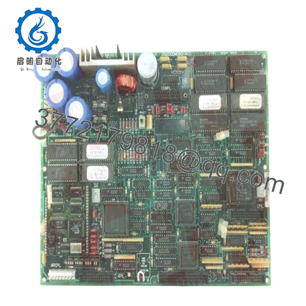
| Model Number | DS200IPCDG1A |
| Product Type | IGBT P3 DB Snubber Card |
| Platform | GE Mark V |
| Primary Function | Snubber and IGBT interface protection |
| Application | GE drive and turbine control systems |
| Connector Type | 4-pin connector interface |
| Hardware Features | High-current protection circuitry |
| Mounting Method | Drive/rack-mounted PCB |
| System Compatibility | Mark V drive systems |
| Cooling Requirement | Cabinet forced-air cooling recommended |
| Operating Temperature | 0 °C to 55 °C typical cabinet environment |
| Storage Temperature | −40 °C to +85 °C |
| PCB Construction | Industrial-grade multilayer PCB |
| Condition Availability | New Surplus / Tested Refurbished |
| Packaging | ESD-safe industrial export packaging |
4. Product Introduction
The GE DS200IPCDG1A is a Mark V snubber and IGBT interface board used in GE industrial drive and turbine control systems. It supports high-current switching protection and interfaces with associated drive control circuitry inside Mark V cabinets.
In field service environments, these boards are commonly replaced during outage maintenance on aging GE drive systems where operators continue maintaining installed Mark V infrastructure instead of performing a full controls migration. Engineers typically retain these boards to preserve cabinet wiring, existing drive logic, and commissioning parameters.

- DS200IPCDG1A
5. Installation & Configuration Guide
Stage 1: Pre-Installation Preparation (Estimated Time: 10–15 Minutes)
⚠️ Safety First
- Coordinate shutdown procedures with operations and electrical maintenance.
- Bring the drive or turbine system into a confirmed safe state.
- Lock out/tag out all associated AC and DC cabinet feeds.
- Wait a minimum of 10 minutes for DC bus capacitor discharge.
❗Do not trust panel indicators alone. Verify the DC bus with a meter before touching the cabinet. I’ve seen charged drive buses stay above 400 V long after shutdown.
Tools Required
- Grounded ESD wrist strap
- PH1 screwdriver
- Fluke 115 multimeter or equivalent
- Insulated gloves rated for cabinet voltage
- Wire labels
- Smartphone for connector photos
Data Backup
- Record cabinet slot location and board orientation.
- Photograph:
- Connector routing
- Ground straps
- Mounting hardware
- Adjacent drive boards
- Document associated drive fault history before removal.
❗Take detailed photos before disconnecting anything. Mark V drive cabinets often contain similar-looking boards positioned inches apart.
Stage 2: Removing the Old Module (Estimated Time: 5–10 Minutes)
- Remove cabinet barriers and protective covers carefully.
- Label all connectors before disconnecting.
- Disconnect the 4-pin connector evenly without twisting the PCB.
- Release retaining screws and mounting hardware.
- Pull the board straight out carefully.
Inspection Checklist
- Inspect connectors for heat damage
- Check for capacitor discoloration
- Look for cracked solder joints
- Verify no conductive dust exists inside the cabinet
⚠️ Note
Keep the original board nearby during startup testing. Even failed boards are useful for confirming jumper and connector orientation.
Stage 3: Installing the New Module (Estimated Time: 10 Minutes)
- Wear the ESD wrist strap before opening the anti-static packaging.
- Verify exact model number: DS200IPCDG1A.
- Confirm hardware revision and connector layout.
Configuration Clone (Crucial)
- Match jumper and connector positions exactly.
- Verify grounding points carefully.
- Confirm snubber circuit orientation matches the original installation.
❗This is one of the easiest places to create a major fault. I’ve seen a technician install the correct board backward in a poorly lit cabinet and immediately trip the drive during startup.
Installation Steps
- Align the board with mounting rails or standoffs.
- Install evenly without flexing the PCB.
- Tighten mounting screws securely.
- Reconnect all connectors using proper alignment.
Self-Checklist
- Model verified
- Connector orientation confirmed
- Grounding restored
- Board mounted securely
- Adjacent wiring clear of heatsinks
Stage 4: Power-On & Testing (Estimated Time: 20 Minutes)
Pre-Power Check
- Verify DC bus voltage is stable before startup.
- Use a multimeter to check for shorts on output rails.
- Confirm cabinet grounding continuity.
Power-On Procedure
- Energize the drive cabinet without enabling motor output initially.
- Observe startup indicators and diagnostic alarms.
- Verify:
- Normal initialization
- No fault LEDs
- Stable drive communication
- Proper gate firing behavior
- Perform controlled dry-run testing.
- Monitor cabinet temperature during initial load conditions.
⚠️ Troubleshooting Notes
- Immediate trip on startup: Suspect connector orientation or snubber mismatch.
- Intermittent drive faults: Check grounding and heatsink contact integrity.
- Communication instability: Verify adjacent drive control board seating.
I’ve watched engineers replace processors and power supplies before realizing the actual issue was one partially seated snubber board creating intermittent gate faults.
Technical Pitfalls & Survival Guide
❗ Firmware & Drive Revision Mismatch
Older Mark V drive systems are extremely sensitive to mixed hardware revisions.
Before replacement:
- Record drive firmware revision
- Verify cabinet BOM
- Check approved board compatibility
I once worked a startup where the replacement board physically fit perfectly but introduced nuisance trips because the drive revision expected a slightly different snubber response profile.
❗ Connector Misalignment
This happens more often than people admit.
Before removal:
- Photograph connector orientation
- Label every cable
- Verify pin alignment manually
Never force connectors into place.
❗ Terminal & Grounding Differences
Some Mark V cabinet revisions use different grounding arrangements.
Always verify:
- Ground strap placement
- Shield grounding
- Connector keying
- Mounting hardware insulation
Do not assume similar boards share identical grounding schemes.
❗ Cabinet Thermal Load
These boards operate in high-current environments.
Verify:
- Cooling fan condition
- Airflow clearance
- Cabinet dust buildup
- Heatsink cleanliness
A partially blocked airflow path can cook a replacement board during the first high-load startup.
❗ Electrostatic Discharge (ESD)
Drive interface boards are highly vulnerable to static damage.
Use:
- Grounded wrist strap
- ESD-safe surface
- Anti-static storage packaging
I once watched a contractor unpack a Mark V board directly on cardboard during winter maintenance season. The board failed immediately under load testing.
Keep these checks in mind and you’ll save yourself 90% of typical rework time.
6. Frequently Asked Questions (FAQ)
Q1: Can I hot-swap the GE DS200IPCDG1A?
No. This board operates inside a high-energy drive environment. Removing or inserting it under power can damage the drive, arc connectors, or destroy associated IGBT circuitry. Always isolate cabinet power fully first.
Q2: Is the DS200IPCDG1A obsolete?
Yes. The Mark V platform is considered legacy GE hardware. Most available inventory now comes from surplus stock, plant decommissioning projects, or specialized automation suppliers.
Q3: Is this board genuinely new or refurbished?
Availability varies by inventory source.
Typical market conditions include:
- New Original / New Surplus
- Tested refurbished
- Exchange-repair stock
Always request:
- Serial photos
- PCB inspection images
- Functional test documentation
- Packaging photos
Some listings online are clearly identified as used or refurbished rather than unused surplus stock.
Q4: What does this board actually do inside the drive?
The DS200IPCDG1A functions as a snubber/protection interface board associated with IGBT switching circuitry in Mark V drive systems. It helps manage transient electrical behavior and protects associated high-current switching components.
Q5: What is the most common installation mistake?
Connector and grounding errors.
Honestly, this is where most field delays happen:
- One connector shifted by a pin
- Missing grounding strap
- Improper seating
- Static damage during handling
The cabinet may still power up normally while hiding intermittent faults that only appear under motor load.
Q6: Why are prices so inconsistent online?
Testing quality and traceability vary heavily in the surplus automation market.
Lower-priced units may:
- Skip load testing
- Have unknown storage history
- Be repaired assemblies
- Lack serial traceability
A visually clean board does not automatically mean electrically healthy.
Q7: What testing is typically performed before shipment?
Standard QC procedures generally include:
- Inbound Inspection & Traceability
- OEM label verification
- Anti-counterfeit inspection
- Connector inspection
- PCB visual audit
- Functional Testing
- Installed into compatible Mark V drive setup
- Power-on diagnostics
- Communication verification
- Load observation testing
- Electrical Testing
- Ground continuity checks
- Insulation resistance testing
- Basic rail stability verification
- Final QC & Packaging
- QC sign-off
- ESD bag sealing
- Reinforced export carton packaging
- QC date labeling
Test photos and startup videos are available upon request.


