
 WhatsApp: +86 16626708626
 Email:
  Phone: +86 16626708626
Description
3. Key Technical Specifications
| Parameter | Value |
|---|---|
| Model Number | DS200KLDAG1ACC |
| Manufacturer | GE General Electric |
| Product Type | Keypad LED Display Board |
| Series | GE Mark V Speedtronic DS200 |
| Functional Description | Keypad / LED / Display Interface |
| LED Count | 32 LEDs |
| Display Count | 7 display modules |
| Dimensions | 8.5 x 11 in |
| Weight | Less than 5 lb |
| Installation Type | Control cabinet PCB mounting |
| Auxiliary Boards | Seven DS200DSPA daughterboards |
| PCB Revision | A-rated primary, C-rated secondary, C-rated artwork |
| Communication | Integrated within Mark V architecture |
| Product Status | Legacy / Obsolete |
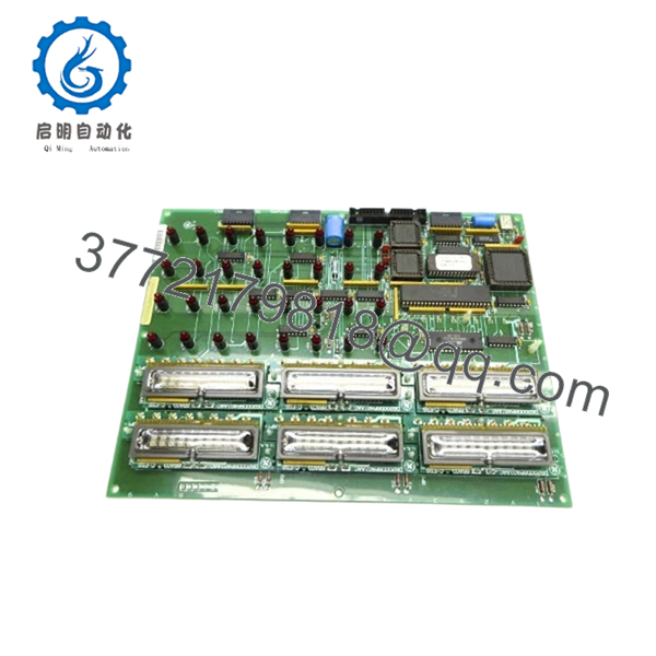
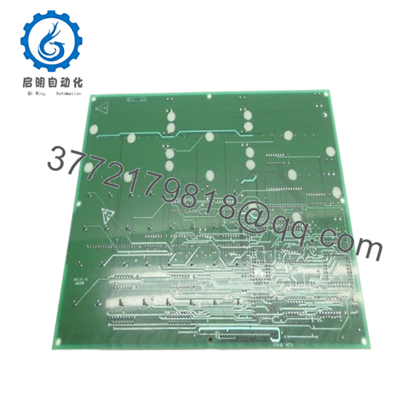
The DS200KLDAG1ACC functions as a display and operator interface board inside GE Mark V turbine control systems. It contains a large primary PCB and seven auxiliary boards interconnected through pin assemblies.
4. Product Introduction
The GE DS200KLDAG1ACC is a Keypad LED Display Board used within GE Mark V Speedtronic turbine and industrial drive control systems. It provides local visual indication and operator interaction through multiple LED arrays and display sections for real-time operating data.
In field deployments of Mark V cabinets, these boards often remain active for decades. Failures usually come from cracked displays, damaged daughterboards, connector fatigue, or accidental handling damage during maintenance. Plants with aging turbine assets commonly keep spare boards because replacement lead times are unpredictable.
5. Installation & Configuration Guide
Stage 1: Pre-Installation Preparation (Estimated Time: 10 minutes)
⚠️ Safety First: Notify operations of downtime. Verify the turbine or drive system has reached a safe state. Apply lock out/tag out procedures and wait 5 minutes minimum for discharge of internal cabinet power sections.
Tools Required
- ESD wrist strap
- PH1 screwdriver
- Fluke 115 multimeter
- Wire labels
- Smartphone for photos
- Flashlight
Data Backup
- Save controller and HMI settings where possible.
- Photograph all board connectors.
- Record revision labels.
- Photograph daughterboard positions.
- Document jumper settings.
⚠️ Mark V systems frequently contain undocumented field changes. I have opened cabinets at 2 AM and found connector reroutes never reflected on electrical drawings.
Stage 2: Removing the Old Module (Estimated Time: 5–10 minutes)
Steps:
- Remove access covers.
- Label all attached connectors.
- Disconnect cables carefully.
- Remove retaining hardware.
- Pull board straight outward.
Inspect for:
- Bent connector pins
- Broken display modules
- Dust buildup
- Heat discoloration
- Loose daughterboard connections
⚠️ Keep the removed board until commissioning completes.
I’ve seen technicians discover undocumented jumper settings after the original board already disappeared into storage.
Stage 3: Installing the New Module (Estimated Time: 5 minutes)
Steps:
- Wear grounded ESD protection.
- Verify exact model: DS200KLDAG1ACC
- Configuration Clone (Crucial): Match all jumper and hardware settings.
- Insert evenly into mounting rails.
- Confirm full seating.
- Reconnect all connectors.
Self-Checklist:
- Jumpers verified
- Wiring secured
- Connectors fully seated
- Mounting hardware installed
❗This is the most common rookie mistake, but experienced engineers get caught too. Take a picture before removal. I can’t stress this enough.
Stage 4: Power-On & Testing (Estimated Time: 10 minutes)
Pre-Power Check
Use a multimeter to confirm no short circuit exists on the 24 V rail.
Power sequence:
- Power cabinet only.
- Observe startup LED sequence.
- Confirm displays initialize.
- Connect engineering workstation.
- Verify communication health.
- Perform display and operator input checks.
Indicators:
- Green RUN: Normal operation
- Red ERR: Fault detected
⚠️ Troubleshooting Note: If displays remain dark or communication faults appear, inspect board revision compatibility and connector seating.
I once watched an engineer spend six hours troubleshooting a display fault that turned out to be one daughterboard connector sitting half a millimeter out of place.

- DS200KLDAG1ACC
- DS200KLDAG1ACC
6. Frequently Asked Questions (FAQ)
Q1. Can I hot-swap this module?
No.
Do not remove or install the DS200KLDAG1ACC while energized. Mark V systems were not designed for live board replacement. Backplane and display circuitry can be damaged during insertion under power.
Q2. Is DS200KLDAG1ACC obsolete?
Yes.
This is a legacy GE Mark V component. Most inventory now comes from surplus stock or tested refurbished units. Availability changes quickly because OEM production has ended.
Q3. Does the ACC suffix matter?
Absolutely.
GE revision suffixes matter more than many technicians expect. The DS200KLDAG1ACC contains multiple revision identifiers that affect compatibility. Only certain revisions maintain backward compatibility.
I’ve seen projects lose two days because someone assumed “same board family” meant identical behavior.
Q4. Will I lose operating logic if I remove this board?
Normally no.
The DS200KLDAG1ACC mainly handles display and operator interaction functions. Primary control logic typically resides elsewhere in the Mark V architecture.
Still, back up everything before touching a cabinet.
Q5. Why is your price lower than OEM historical pricing?
Because this market works differently after product discontinuation.
Pricing now depends on:
- New surplus availability
- Repair history
- Functional testing performed
- Included warranty
- Geographic inventory source
Two identical boards can have very different histories.
Q6. How are legacy GE boards tested before shipment?
Standard verification sequence:
Inbound Inspection & Traceability
- Verify source records
- Check labels and revisions
- Anti-counterfeit inspection
- Inspect for corrosion or rework marks
Live Functional Testing
- Tested on compatible GE hardware where available
- LED and display verification
- Communication testing
- Simulated operational testing
- Continuous run testing >24 hours
Electrical Testing
- 500 V insulation resistance test (>10 MΩ)
- Ground continuity checks
- Hipot testing if applicable
Firmware & Configuration Verification
- Revision documentation
- Jumper configuration recording
Final QC
- Inspector sign-off
- Anti-static packaging
- Bubble protection
- Heavy-duty shipping carton
Test videos and inspection photos are available upon request.
Q7. What installation mistake causes the most downtime?
❗Connector seating and jumper mismatches.
This board includes auxiliary daughterboards and multiple interconnections. A connector that looks installed can still be slightly unseated.
Keep these checks in mind and you’ll save yourself 90% of typical rework time.


