
 WhatsApp: +86 16626708626
 Email:
  Phone: +86 16626708626
Description
3. Key Technical Specifications
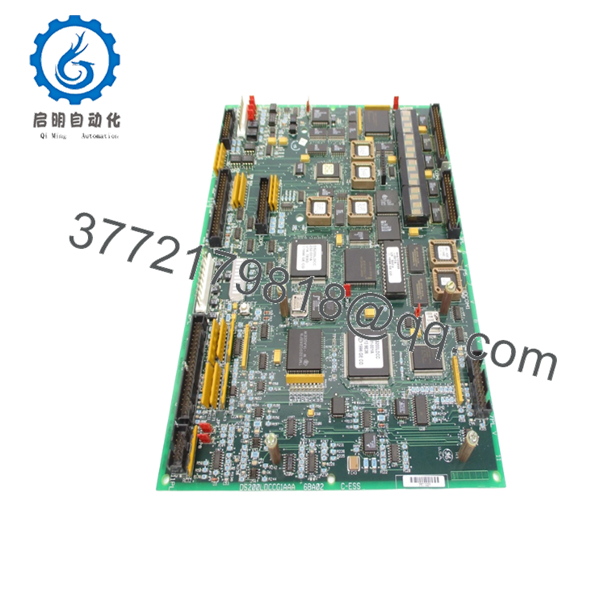
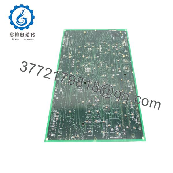
DS200LDCCG1AAA functions as the primary control and communications processor board for GE DIRECTO-MATIC drive and excitation systems. It handles drive control, motor processing, I/O handling, and LAN communications through dedicated onboard processors.
| Parameter | Value |
|---|---|
| Manufacturer | GE Motors & Industrial Systems |
| Model | DS200LDCCG1AAA |
| Functional Acronym | LDCC |
| Product Type | Drive Control / LAN Communications Board |
| Series | DIRECTO-MATIC 2000 / EX2000 |
| Instruction Manual | GEI-100216 |
| Processor Count | 4 onboard processors |
| Drive Control Processor | DCP at U1 |
| Motor Control Processor | MCP at U21 |
| Co-Motor Processor | CMP at U35 |
| LAN Processor | LCP at U18 |
| Supported Bus Systems | DLAN+, DLAN, Genius, CPL, C-bus |
| Power Requirement | +5 VDC, 7 A |
| Power Consumption | Approx. 20 W |
| Operating Temperature | −10 °C to +60 °C |
| Isolation Voltage | 1,500 VAC |
| PCB Protection | G1 normal coating |
| Warranty | Typically 12 months |
The LDCC board acts as the processing center of the drive system and integrates drive regulation, LAN communications, diagnostics, and application execution.
4. Product Introduction
GE DS200LDCCG1AAA is a Drive Control/LAN Communications Board used in GE DIRECTO-MATIC 2000 and EX2000 excitation systems. It serves as the central processing platform for drive logic, operator functions, LAN communications, and I/O handling.
In field deployments, the LDCC board is often treated as the “brain” of the drive system. When this board fails, symptoms rarely stay isolated. Communication faults, unstable control loops, and operator interface failures can appear simultaneously. During outages, I strongly recommend matching the full DS200LDCCG1AAA revision rather than assuming any LDCC board will work.

- DS200LDCCG1AAA
- DS200LDCCG1AAA
5. Installation & Configuration Guide
Stage 1: Pre-Installation Preparation (Estimated: 10 minutes)
⚠️ Safety First: Notify operations of planned downtime. Verify the drive and excitation systems are in a safe state. Apply lockout/tagout procedures. Wait at least 5 minutes for capacitor discharge.
Tools Required
- ESD wrist strap
- PH1 screwdriver
- Fluke 115 multimeter
- Wire labels
- Smartphone for documentation photos
- ESD work mat
- Flashlight
Data Backup
- Export drive configuration and parameter files.
- Record slot locations.
- Photograph all connectors.
- Photograph jumper and switch positions.
- Record firmware and revision data.
⚠️ On older GE systems, I frequently find undocumented field modifications and handwritten jumpers that never made it into drawings.
Stage 2: Removing the Old Module (Estimated: 5 minutes)
- Remove front cabinet covers.
- Label every connector before removal.
- Disconnect cables carefully.
- Release retention hardware.
- Pull board straight out.
Inspect:
- Backplane connector pins
- Dust contamination
- Heat damage
- Connector wear
⚠️ Keep the old board nearby until startup completes.
I have seen technicians send failed boards for repair immediately, only to discover they forgot to document jumper settings.
Stage 3: Installing the New Module (Estimated: 10 minutes)
- Wear grounded ESD protection.
- Verify exact model: DS200LDCCG1AAA
- Configuration Clone (Crucial): Copy every jumper and switch exactly.
Pay attention to:
- Bus settings
- Network addressing
- Hardware jumpers
- Processor configuration selections
This is the most common rookie mistake, but it happens constantly. Take a picture before you pull it. I can’t stress this enough.
- Insert board carefully.
- Confirm connector engagement.
- Reconnect all wiring.
Self-Checklist
- DIPs match
- Wiring secured
- Lock tabs engaged
Stage 4: Power-On & Testing (Estimated: 10 minutes)
Pre-Power Check
Use a multimeter to verify no shorts exist on control power rails.
Power-up sequence:
- Energize cabinet only
- Observe startup LEDs
- Connect engineering workstation
- Verify LAN communication
- Confirm processor diagnostics
- Dry-run I/O functions
⚠️ Troubleshooting Note: If multiple communication alarms appear after startup, suspect firmware mismatch before replacing healthy hardware.
I watched one project lose almost two days because a replacement board moved between firmware generations. The team kept replacing I/O modules while the actual problem sat on the processor board. That lesson sticks with you.
SOP Quality Transparency
Inbound Inspection & Traceability
- Verify OEM shipment documentation and serial records.
- Perform anti-counterfeit inspection.
- Verify labels and holograms.
- Inspect for corrosion, scratches, rework marks, and UV yellowing.
- Audit manuals and certificates.
Live Functional Testing
Testing performed on a GE-compatible drive simulation rack where available.
Procedure:
- Power-on self-test
- LED verification
- LAN handshake checks
- I/O simulation
- Continuous operation exceeding 24 hours
- Thermal monitoring
Official Test Report generated after testing.
Electrical Parameter Testing
- 500 V Megger insulation resistance >10 MΩ
- Ground continuity verification
- Hipot testing if applicable
Firmware & Configuration Verification
- Record firmware revisions
- Photograph jumpers
- Archive hardware settings
Final QC & Packaging
- QC signoff
- ESD anti-static packaging
- Bubble wrap protection
- Heavy-duty corrugated carton
- QC date labeling
Test videos and photos are available upon request.
Technical Pitfall & Survival Guide
❗ Firmware Revision Mismatch
Document firmware before pulling hardware.
I’ve seen projects where replacing V2.8 with V3.1 created communication timeout alarms for two days.
❗ DIP Switch / Jumper Errors
Take photos first.
Simple issue. Happens constantly.
❗ Terminal Block / Wiring Assumptions
Even similar GE boards occasionally change connector assignments.
Never wire from memory.
❗ Power Draw Margin
Maintain at least a 20% supply reserve.
Add enough I/O and communication modules and your power budget disappears faster than expected.
❗ ESD Damage
Wear a grounded wrist strap.
I once watched an engineer handle a processor board in dry winter air without grounding. Cabinet power came on and smoke appeared instantly. Thousands of dollars gone in ten seconds.
Keep these checks in mind and you’ll save yourself 90% of typical rework time.
6. Frequently Asked Questions (FAQ)
Q1: Can I hot-swap this module?
No.
Do not hot-swap the LDCC board. Removing processor hardware under power risks backplane damage and communication faults.
Q2: Is DS200LDCCG1AAA obsolete?
Yes.
DS200LDCCG1AAA belongs to GE legacy drive and excitation systems. Current availability depends heavily on surplus inventory and specialized industrial suppliers.
Q3: Is this genuinely new or refurbished?
Depends on inventory source.
New Surplus generally means unused inventory from older projects. Refurbished hardware previously operated in service and later passed testing. Request test reports and actual photographs.
Q4: Will I lose programming logic during replacement?
Potentially, depending on configuration architecture.
Application data and customer configuration may reside on the LDCC board. Before shutdown, export configuration files and verify backup integrity.
Q5: Why is your price lower than OEM factory pricing?
Inventory age.
Many suppliers purchased stock years ago and distribute remaining inventory today. Lower pricing alone does not indicate lower quality.
Q6: What communication networks does this board support?
The LDCC processes DLAN+, DLAN, Genius, CPL, and C-bus architectures through dedicated interfaces and processors. Verify existing system architecture before replacement.
Q7: Why is this board considered so critical?
Because it handles drive processing, I/O handling, and LAN communications simultaneously. When an LDCC board fails, multiple unrelated alarms often appear together, which makes troubleshooting harder than most engineers expect.


