
 WhatsApp: +86 16626708626
 Email:
  Phone: +86 16626708626
Description
3. Key Technical Specifications
| Parameter | Value |
|---|---|
| Model Number | DS200NATOG3A |
| Manufacturer | GE Industrial Systems |
| Product Type | Voltage Feedback Scaling Board |
| Series | LS2100 Static Starter Control |
| Primary Function | Voltage feedback attenuation and scaling |
| Input Voltage Ranges | 1,200 V, 2,200 V, 3,300 V, 4,200 V, 6,900 V (configurable) |
| Protection | Integrated MOV surge protection |
| Logic Supply | 24 VDC |
| Interface | 20-pin ribbon connector |
| Agency Approvals | UL, CE (EC), CSA |
| Application | SCR Bridge Voltage Feedback |
| Reference Manual | GEI-100225 |
| Operating Environment | Industrial control cabinets |
4. Product Introduction
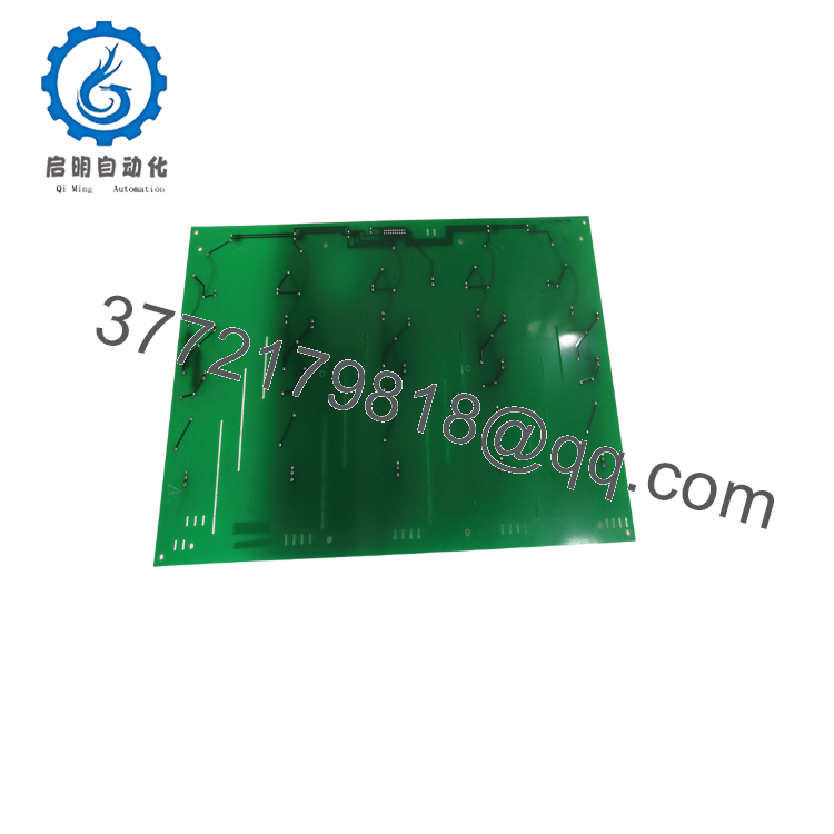
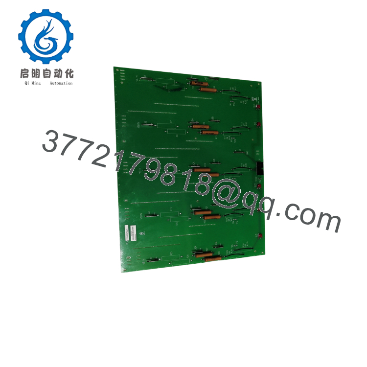
The GE DS200NATOG3A is a Voltage Feedback Scaling Board used in GE LS2100 static starter systems. Its primary purpose is to attenuate high AC and DC voltages from the SCR bridge into low-level feedback signals that the control processor can measure accurately for firing angle regulation and system protection.
The board uses configurable resistor networks and integrated surge suppression to support multiple medium-voltage applications. During field replacements, engineers should verify both the configured voltage range and the complete part number before installation, as installing an incorrect board configuration can produce inaccurate voltage feedback and protection trips.

- DS200NATOG3A
- DS200NATOG3A
5. Installation & Configuration Guide
Stage 1 – Pre-Installation Preparation (10 minutes)
⚠️ Safety First
- Notify operations of the planned shutdown.
- Lock out and tag out all incoming power.
- Wait at least 5 minutes for capacitor discharge.
- Verify zero voltage using a calibrated multimeter.
Tools Required
- ESD wrist strap
- PH1 screwdriver
- Digital multimeter (Fluke 115 or equivalent)
- Wire markers
- Smartphone for documentation
Data Backup
- Record controller parameters.
- Photograph all ribbon cables.
- Photograph resistor jumper settings.
- Record cabinet location and board position.
Stage 2 – Removing the Existing Board (5 minutes)
- Remove cabinet covers.
- Label every connector before removal.
- Disconnect the ribbon cable carefully.
- Remove mounting hardware.
- Pull the board straight out without bending connectors.
- Inspect mating connectors for contamination or damage.
⚠️ Keep the original board until commissioning has been completed successfully.
Stage 3 – Installing the New Board (10 minutes)
- Connect your ESD wrist strap.
- Verify the complete model number is DS200NATOG3A.
- Copy every jumper and resistor configuration from the original board.
- Install the board squarely into its mounting position.
- Secure mounting screws.
- Reconnect ribbon cables and verify connector orientation.
Self-Checklist
- ✔ Correct model verified
- ✔ Jumper settings duplicated
- ✔ Ribbon cable fully seated
- ✔ Mounting secure
- ✔ Cabinet grounding verified
Stage 4 – Power-On & Testing (10–15 minutes)
Pre-Power Checks
- Check 24 VDC control supply.
- Inspect for short circuits.
- Verify connector seating.
Startup Procedure
- Energize the control cabinet.
- Observe controller diagnostics.
- Confirm stable voltage feedback readings.
- Compare measured values with expected system voltage.
- Run commissioning diagnostics.
- Verify SCR bridge operation under no-load conditions.
⚠️ Troubleshooting
- Incorrect voltage readings: Verify resistor configuration.
- Protection trips immediately: Confirm selected voltage attenuation range.
- Communication errors: Inspect ribbon cable and connector alignment.
- Unstable measurements: Check MOV protection devices and connector integrity.
6. Frequently Asked Questions (FAQ)
Q1. Can I hot-swap the DS200NATOG3A?
No. This board interfaces with high-energy voltage feedback circuits. Removing or inserting it under power can damage both the board and the control system. Always isolate the cabinet first.
Q2. Is this model obsolete?
Yes. The DS200NATOG3A belongs to the legacy GE LS2100 product family. Genuine new surplus inventory is limited, although tested refurbished units remain available through industrial automation suppliers.
Q3. Why are there multiple voltage configurations?
The onboard resistor network can be configured for 1,200 V, 2,200 V, 3,300 V, 4,200 V, or 6,900 V systems. Installing an incorrect configuration will produce inaccurate voltage scaling and may trigger protective shutdowns.
Q4. Will replacing this board erase my control program?
No. The board performs analog voltage scaling only. PLC or turbine control logic is stored elsewhere, but documenting the original hardware configuration before replacement remains good engineering practice.
Q5. What is the primary purpose of this board?
It converts high-voltage AC and DC signals from the SCR bridge into scaled feedback signals that the controller uses for voltage regulation, SCR firing control, and protective monitoring.
Q6. Why is New Surplus pricing usually lower than historical OEM pricing?
Most New Surplus inventory originates from cancelled projects, plant expansions, or excess OEM inventory. These are genuine unused components but are no longer in active production, allowing distributors to offer them below original factory pricing.
Q7. What should I verify before returning the system to service?
An experienced field engineer should confirm:
- Correct board revision
- Correct voltage attenuation configuration
- Jumper settings match the original board
- Ribbon cable orientation
- Stable 24 VDC supply
- Cabinet grounding
- Accurate voltage feedback readings during commissioning
These verification steps eliminate the majority of startup problems encountered after replacing a voltage feedback scaling board.



