
 WhatsApp: +86 16626708626
 Email:
  Phone: +86 16626708626
Description
3. Key Technical Specifications
| Parameter | Specification Value |
| Functional Acronym | NATO (Digital I/O Application Board) |
| Group / Configuration | G3 (Group 3 specific circuit layout) |
| Revision Assembly | ACB (Includes structural backward-compatible updates) |
| Signal Density | Multiple distributed digital logic pathways |
| Isolation Design | Channel-to-channel optical and galvanic isolation provisions |
| Onboard Connectors | Vertical pin ribbon cable headers and screw terminal access |
| Coating Protection | Factory-applied industrial conformal coating |
| System Interconnect | Directly links to the central LOC (Local I/O) core or dynamic logic rack |
| Diagnostic Traces | Integrated hardware test points for voltage monitoring |
| Input Current Limits | Tailored for low-voltage logic signal processing |
| Ambient Limits | Operates reliably at up to 60°C inside sealed control cabinets |
4. Product Introduction & Supply Chain Strategy
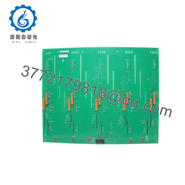
The GE DS200NATOG3ACB is a specialized digital input/output application board engineered for the legacy Speedtronic Mark V gas and steam turbine control environment. Operating as a critical Group 3 (G3) component, this module acts as an specialized interface that processes, filters, and routes discrete control signals between the core control rack hardware and the primary field termination blocks. Featuring an factory-applied conformal coating and the stable ACB revision layer, it ensures clean logic state execution and noise-free communication for high-reliability turbine protection schemes.
From an engineering inventory perspective, acquiring this card as a New Surplus asset is a necessary step to protect legacy systems against unexpected component failure. Because the Mark V series is completely obsolete and no longer supported by factory production lines, relying on used or poorly refurbished components exposes your control loop to latent timing faults and unexpected breakdowns. Sourcing a verified New Surplus board optimizes your Total Cost of Ownership (TCO) by providing zero-wear hardware reliability, eliminating the steep overhead expenses of emergency plant shutdowns, and securing continuous facility availability.

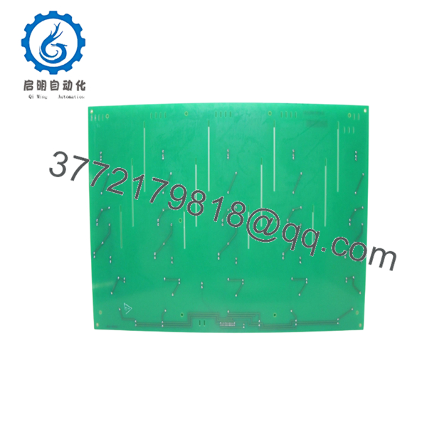
- DS200NATOG3ACB
- DS200NATOG3ACB
5. Installation & Configuration Guide
Stage 1: Pre-Installation (Prep & Safety)
- Execute an absolute power-down sequence on the Mark V control panel enclosure. Isolate and tag out all auxiliary power lines and external interrogation voltages feeding the card.
- Confirm that you are wearing a fully functional, grounded ESD wrist strap before handling the replacement module.
- Document the existing layout. Photograph all multi-conductor ribbon cables, individual ground wires, and the precise orientation of any hardware jumpers or trace-selection pins.
Stage 2: Removal
- Disconnect the front-panel ribbon cables by spreading the side retention clips outward and lifting the cable plugs vertically out of their headers.
- Loosen and remove the mounting screws anchoring the board to the nylon standoffs inside the cabinet frame.
- Pull the card straight out away from its mounting surface, ensuring the rear solder traces do not catch on any internal metal edges or structural frame pieces.
Stage 3: Installation (Clone & Seat)
- Compare the physical hardware jumper settings on the new DS200NATOG3ACB against the pulled board. Replicate every jumper placement precisely to guarantee configuration parity.
- Align the board mounting holes with the nylon standoffs in the control cabinet.
- Hand-tighten the retention screws across the board frame in a diagonal sequence, then secure them firmly without overtightening to prevent cracking the board.
- Press the ribbon cables straight down into the card headers until the outer retention clips snap closed.
Stage 4: Power-On & Testing
- Re-energize the main cabinet circuit breakers and supply lines to the Mark V control panel.
- Verify that the onboard status indicators or adjacent rack LEDs light up in their normal operational sequences.
- Access the system diagnostics using your HMI or core programming interface to verify that no board communication dropouts or I/O configuration faults are active.
6. Firmware/Software Versions & Upgrade Notes
- EEPROM Configuration Matching: The DS200NATOG3ACB is a hardware interface card that reads its system layout from the configuration parameters compiled within the core software logic. Ensure your active application code package accounts for the specific Group 3 configuration properties.
- Revision Backward Compatibility: The ACB revision code designates a fully backward-compatible advancement over previous iterations (such as AC or ACBA). It can directly replace older Group 3 versions without requiring structural wiring changes or soft-logic rebuilds.
- Configuration Risks: Never change jumper configurations or adjust internal board links while the turbine is running. Making physical configuration adjustments during active operations can cause sudden signal changes, which will trigger emergency fail-safe shutdowns or asset damage.
7. Frequently Asked Questions (FAQ)
What makes this “New Surplus” board different from standard refurbished inventory?
Our New Surplus cards are unused, zero-hour components sourced from corporate overstock, uninstalled plant spares, or canceled infrastructure budgets. They have been kept in secure, climate-controlled environments and remain in their original anti-static packaging. Refurbished parts are extracted from decommissioned systems and are highly vulnerable to thermal wear, component drift, and micro-fractures in old solder points.
Why is this legacy card priced higher than typical used equipment online?
The NATO application board is an obsolete component that is critical to keeping older Mark V systems running. Sourcing an unverified used card poses a significant financial risk; a single logic failure can keep a turbine offline for days. This New Surplus board provides factory-level component integrity, offering high return on investment by ensuring immediate operational stability and protecting against high unscheduled downtime costs.
Can I use the DS200NATOG3ACB to replace a different group version, such as a G1 or G2 board?
No. The G3 designation identifies a specific circuit component layout, termination pathway, and electrical load configuration. Attempting to substitute a Group 3 card into a slot meant for a Group 1 or Group 2 module will cause serious signal routing errors and can lead to permanent component damage or severe system faults within the control rack.
What is the role of the conformal coating on this module?
The conformal coating is a specialized, thin protective layer applied across the entire circuit board assembly. This coating seals the surface-mount components, traces, and solder joints against airborne contaminants, moisture, conductive dust, and localized corrosion. It is an essential feature for maintaining long-term signaling stability inside demanding industrial environments.
What should I check first if the board throws a digital signaling error after installation?
If you encounter an error post-installation, recheck the ribbon cable seating first. Ensure that the connectors are pushed completely into the headers and that the side retention clips are fully locked. If the connection is solid, double-check that your hardware jumper blocks on the new card match the configuration of the original board exactly. Mismatched jumpers are the most common cause of signal routing and identification errors.



