
 WhatsApp: +86 16626708626
 Email:
  Phone: +86 16626708626
Description
3. Key Technical Specifications
| Parameter | Specification / Value |
| Manufacturer | GE (General Electric) |
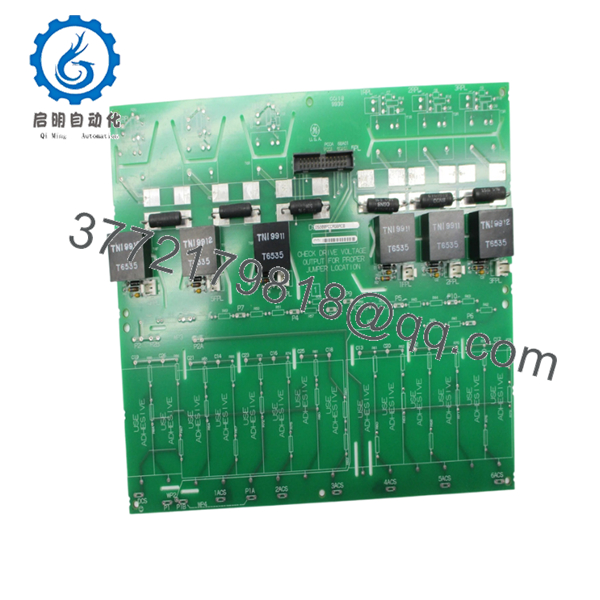
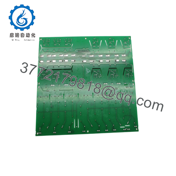
| Part Number | DS200PCCAG6A |
| System Compatibility | Mark V Speedtronic / Direct Digital Control (DDC) Drives |
| Application | Silicon-Controlled Rectifier (SCR) Power Conversion Modules |
| Input Channels | Multi-channel scaling for voltage and current feedback |
| Isolation Rating | High-voltage galvanic isolation between power and control planes |
| On-Board Diagnostics | LED indicator array for active power supply monitoring |
| Hardware Variant | G6 Configuration (specific scaling and connector profile) |
| Operating Temperature | 0 to +50°C |
| Storage Temperature | −40 to +70°C |
4. Product Introduction & Supply Chain Strategy
The GE DS200PCCAG6A is a Power Connect Control Board built for the Mark V Speedtronic control platform and legacy GE drive systems. This module functions as the main interface between high-power Silicon-Controlled Rectifier (SCR) bridge assemblies and the low-voltage microprocessor control circuits. It routes gate firing pulses directly to the power bridge while scaling down high-voltage current and voltage feedback signals via precision attenuation networks. This ensures that the digital control core receives clean, isolated feedback data required to maintain system stability in power generation and heavy industrial drive applications.
From a supply chain standpoint, procuring a verified New Surplus DS200PCCAG6A is an essential step toward mitigating obsolescence risks. Because the Mark V series is an end-of-life platform no longer supported with active factory production, lead times for unexpected failures can span weeks or months. Relying on refurbished alternatives exposes your operations to hidden component wear and breakdown risks. Choosing New Surplus provides an efficient Total Cost of Ownership (TCO) advantage, giving you unused, factory-reliable hardware that maintains plant uptime without the high price tags of remaining emergency OEM stock.
5. Installation & Configuration Guide
Stage 1: Pre-Installation (Prep & Safety)
- Implement a strict lock-out/tag-out (LOTO) procedure on all incoming AC lines, DC buses, and auxiliary 125 VDC control supplies feeding the drive enclosure.
- Confirm that all residual voltage in the dc-link capacitors and SCR bridges has completely dissipated using a calibrated digital multimeter.
- Fasten a grounded, corded ESD wrist strap to a bare metal point on the cabinet frame before unpacking hardware.
- Photograph the original board layout, specifically noting the orientation of high-voltage ribbon cables, wire runs, and jumper pins.
Stage 2: Removal
- Systematically label all wiring bundles and multi-pin ribbon cables linked to the board headers to ensure proper orientation during reassembly.
- Carefully unplug the high-voltage signal cables and power distribution lines from their plugs, taking care not to strain the wiring insulation.
- Unscrew the mounting screws that lock the PCB corners to the internal cabinet backplate standoffs.
- Withdraw the module smoothly from the enclosure, ensuring the rear traces do not drag against structural metal, and place it immediately into a static-shielding bag.
Stage 3: Installation (Clone & Seat)
- Remove the new DS200PCCAG6A card from its static-safe packaging while working within an ESD-protected zone.
- Review the hardware revision suffix (G6A) and adjust all onboard jumpers or configuration links to match the previous module exactly.
- Position the board over the mounting standoffs, ensuring it sits flat without bending or mechanical tension across the substrate.
- Tighten the retaining screws snugly, using care not to over-torque or crack the circuit board.
- Reconnect all signal wires, ribbon cables, and power connections to their proper headers as noted during removal.
Stage 4: Power-On & Testing
- Complete a comprehensive visual inspection to confirm that no stray wire strands or tools remain on or near the board.
- Restore power to the low-voltage logic supply lines first, keeping the main high-voltage SCR power bus completely isolated.
- Verify that the onboard diagnostic LEDs illuminate correctly and that no system fault or overcurrent flags register on the central controller display.
- Run a simulated drive command sequence via your software console to check signal feedback tracking before energizing the main power circuit.

- DS200PCCAG6A
- DS200PCCAG6A
6. Firmware/Software Versions & Upgrade Notes
The DS200PCCAG6A operates using precise analog scaling networks and hardwired logic layouts mapped to distinct hardware generations. The G6A alphanumeric designation marks the specific scaling, attenuation profiles, and plug configurations built into this card version.
When replacing an existing power connect card, using an identical revision tier is crucial to avoid signal measurement errors. Installing an unapproved or mismatched revision can cause misread voltage or current feedback loops, leading to false overcurrent trips, gate pulse mistiming, or damage to the SCR bridge. Ensure a full configuration and parameter dump is archived from your drive diagnostic terminal before running any physical component swaps.
7. Frequently Asked Questions (FAQ)
What defines the “New Surplus” condition of this GE DS200PCCAG6A board?
A New Surplus unit is an entirely unused, original OEM component sourced from surplus supply channels. It is not a used part pulled from a decommissioned facility, and it has not been repaired or refurbished. The card has been kept in climate-controlled storage, preserving its original structural integrity, trace insulation, and component lifespan.
Why should we avoid buying refurbished boards for our power connect circuits?
Power connect boards operate near high-voltage circuits and handle high-frequency gate pulses that generate significant thermal stress over time. Refurbished boards often carry hidden wear, including micro-cracks in trace pathways or drift in scaling resistors that pass standard bench checks but fail under real-world operating loads. Investing in New Surplus avoids the risk of unplanned downtime failures that can quickly surpass any minor upfront savings.
Is this specific board model still manufactured by GE?
No, the GE Mark V system and its associated drive components are legacy hardware that has been officially discontinued. New units are no longer produced by the factory. Because of this limited supply, keeping 1 or 2 verified units on-site within your plant’s critical buffer stock is a key step to prevent lengthy outages when active online modules require replacement.
Are adjustments required on the board during installation?
Yes. You must check and replicate all jumper selections from your old card onto the new DS200PCCAG6A. These jumpers set the scaling parameters for the voltage and current feedback loops to match your specific motor or turbine drive size. Incorrect jumper settings will cause the controller to receive skewed feedback values, resulting in immediate fault trips.
What kind of warranty accompanies this component?
We provide a comprehensive commercial warranty with this New Surplus DS200PCCAG6A board that matches or exceeds standard OEM coverage periods. This offers your engineering and procurement teams solid protection and peace of mind, delivering a level of reliability that used or refurbished parts cannot guarantee.


