
 WhatsApp: +86 16626708626
 Email:
  Phone: +86 16626708626
Description
3. Key Technical Specifications
| Parameter | Value |
| Input Channels | 10 Total (RTD or Potentiometer) |
| Termination Type | Fixed Screw-Terminal Blocks |
| Wire Gauge Support | 12 to 22 AWG |
| Interface Connector | 50-pin ribbon cable (to I/O board) |
| Dimensions | 8.50 in x 4.50 in (Standard Mark V footprint) |
| Signal Filtering | Passive RC filtering per channel |
| Mounting | DIN rail or stand-off mounting in core , , or |
| Compliance | Original OEM Manufacturing Specs |
4. Product Introduction & Supply Chain Strategy
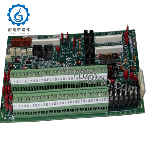
The GE DS200PTBAG1BBA is a specialized terminal base board utilized within the Mark V Speedtronic turbine control system. It serves as the physical landing point for field wiring, specifically handling temperature-sensitive RTD inputs and position-sensing potentiometers. By providing a clean interface between rugged field cables and sensitive control electronics, it ensures accurate feedback for turbine governor control and auxiliary systems.
From a strategic maintenance perspective, sourcing the DS200PTBAG1BBA as New Surplus is the most effective way to extend the lifecycle of a Mark V panel. Because terminal boards are passive components, they are often overlooked until a terminal strip strips or a trace develops high resistance due to atmospheric corrosion. Refurbished boards frequently suffer from weakened screw terminals or “cold” solder joints that lead to intermittent signal drops. Utilizing New Surplus inventory eliminates these variables, ensuring a secure, gas-tight connection that matches the original factory reliability standards.
5. Installation & Configuration Guide
Stage 1: Pre-Installation (Prep & Safety)
Ensure the turbine is in a safe lockout state. Before disconnecting any wires, label every cable according to its terminal number (1–44). Use an ESD-safe wrist strap and verify you have the correct small-tip slotted screwdriver for the terminal blocks.
Stage 2: Removal
Disconnect the 50-pin ribbon cable from the header. Unscrew the field wiring from the terminal strips. Remove the screws securing the DS200PTBAG1BBA to the mounting stand-offs or DIN rail bracket. Take care not to drop screws into the lower sections of the control cabinet.
Stage 3: Installation (Clone & Seat)
Compare the jumper positions (JP1, JP2, etc.) on the old board with the new DS200PTBAG1BBA. Move the jumpers on the new board to match the old configuration exactly—these settings define the signal type (RTD vs. Pot). Mount the new board and reconnect the field wiring, following your labels to ensure correct polarity.
Stage 4: Power-On & Testing
Reconnect the ribbon cable and restore power. Use the Mark V operator interface or HMIs to check for “High/Low Limit” alarms. Verify that the temperature or position readings from the PTBA board are consistent with ambient conditions or known physical positions.

- DS200PTBAG1BBA
6. Firmware/Software Versions & Upgrade Notes
- Passive Board: The DS200PTBAG1BBA is a passive terminal board and does not contain programmable firmware.
- Revision Logic: The “G1BBA” suffix indicates the specific group and revision. While often interchangeable with “G1AAA” versions, always verify the jumper map on the silk-screened diagram, as minor revisions can occasionally change jumper numbering.
- Warning: Ensure the ribbon cable is seated squarely. An offset connection can short the 5V or 24V supply rails, potentially damaging the connected I/O processor board.
7. Frequently Asked Questions (FAQ)
Q: Can I use this board for 3-wire RTDs?
A: Yes, the DS200PTBAG1BBA supports standard 3-wire RTD configurations. Refer to your system’s specific elementary wiring diagrams for the correct terminal assignments to ensure lead-wire compensation functions correctly.
Q: Is it safe to buy a “New Surplus” board for a system this old?
A: Absolutely. In fact, it is safer than buying a “recently repaired” board. New Surplus boards have been stored in controlled environments and have never been subjected to the thermal cycling of a running plant. This preserves the integrity of the copper traces and terminal connectors.
Q: Why are there so many jumpers on this board?
A: The PTBA is designed to be versatile. The jumpers allow the board to be configured for different input ranges and sensor types. Without setting these correctly, your controller may see a “floating” signal or an out-of-range error.
Q: Do you provide the mounting plastic stand-offs with the board?
A: Typically, terminal boards are sold as the PCB assembly only. We recommend retaining the mounting hardware from your existing board, as these are standard industrial stand-offs.
Q: What is the warranty on this legacy GE part?
A: We provide a 2-year functional warranty on this New Surplus DS200PTBAG1BBA. We stand by the “zero-hour” condition of our legacy inventory.


