
 WhatsApp: +86 16626708626
 Email:
  Phone: +86 16626708626
Description
Key Technical Specifications
| Parameter | Value |
|---|---|
| Manufacturer | General Electric |
| Model | DS200RTBAG3AFB |
| Common Board Name | RTBA Relay Terminal Board |
| Control System Family | GE Mark V Speedtronic turbine control system |
| Primary Function | Relays discrete turbine-control signals between control electronics and field wiring |
| Total Relay Count | 10 relays |
| Relay Positions | K20 through K29 |
| DPDT Relays | K20–K26, 7 relays |
| DPDT Contact Form | 2 Form C contacts per relay |
| DPDT Contact Rating | 10 A, reported by aftermarket technical reference |
| 4PDT Relays | K27–K29, 3 relays |
| 4PDT Contact Form | 4 Form C contacts per relay |
| 4PDT Contact Rating | 1 A per contact, reported by aftermarket technical reference |
| Relay Coil Voltage | 115 V AC |
| Surge Protection | 130 V AC MOV protection reported across relay circuits |
| Field Connection Capacity | Up to 52 connector/terminal positions reported; verify with physical board and wiring drawings |
| Connector References | CPH, CPN, Y9–Y35, K20–K26, RX1–RX7, X2, and 115 V connections reported in aftermarket documentation |
| Configuration | Berg jumpers used to select internal or external relay supply options |
| Printed Circuit Board Group | G3 board group designation |
| Approximate Dimensions | 305 mm W × 254 mm D, reported by an aftermarket listing; verify actual board before packing or panel-fit decisions |
| Application | Turbine trips, relay outputs, solenoid circuits, lockout functions, auxiliary control commands, and discrete interface circuits |
| Lifecycle Status | Obsolete GE Mark V hardware; limited surplus and refurbished supply |
Aftermarket technical references identify DS200RTBAG3AFB as a GE Mark V RTBA relay terminal board with ten 115 V AC-coil relays: seven 10 A DPDT relays at K20–K26 and three 1 A 4PDT relays at K27–K29. The same references report movable Berg jumpers for internal/external power-source selection and 130 V AC MOV relay protection. Verify values against the physical board and approved Mark V drawings before field installation.
Product Introduction
The GE DS200RTBAG3AFB is an RTBA relay terminal board used in GE Mark V Speedtronic turbine-control systems. It transfers discrete commands between the control cabinet and field devices through ten electromechanical relays. Typical circuits include turbine trip paths, auxiliary relay outputs, lockout solenoids, reset solenoids, test circuits, and other field-interface commands associated with gas or steam turbine control.
This board is a configuration-controlled Mark V spare, not a generic relay PCB. Match the full DS200RTBAG3AFB part number, G3 board group, relay coil voltage, connector arrangement, jumper settings, rack location, and existing wiring before ordering. A visually similar RTBA board can have a different revision, relay configuration, or terminal mapping.
Troubleshooting Quick Reference
| Symptom | Possible Cause | Relevance to This Part | Quick Check Method | Recommendation |
|---|---|---|---|---|
| One field solenoid or relay does not energize | Open load coil, blown fuse, failed interposing relay, broken wire, loose terminal, failed RTBA relay contact | ⚠️ Medium | Verify command state in Mark V diagnostics. Measure voltage at the board output terminal and directly across the field load. Check load-coil resistance only with power isolated. | Repair the field circuit first. Replace the board only if the RTBA coil is commanded and output contacts fail to transfer under a verified load condition. |
| Several outputs fail together | Lost 115 V AC relay supply, open common, blown fuse, connector issue, power-selection jumper error | ⚠️ Medium | Measure the correct 115 V AC supply at the applicable RTBA supply terminals and check jumper positions against the approved Mark V drawing. | Check supply, common wiring, fuses, and jumper configuration before replacing DS200RTBAG3AFB. |
| Relay clicks but field device remains off | Worn or burned contact, open downstream wiring, failed coil or actuator, terminal connection issue | ✅ Medium | Listen for relay pickup, confirm output voltage across the correct switched contacts, and compare with a known-good channel. | If coil energizes but contacts do not pass voltage under a valid load, the relay contact set or board may be defective. |
| Field device remains energized after command drops | Welded relay contacts, external wiring cross-connection, stuck contactor, field-device mechanical fault, controller output still active | ✅ High | Place the turbine system in an approved maintenance state. Confirm diagnostic command status, then measure voltage at the RTBA contact output and field device. | Treat as a safety-critical condition. Determine whether the voltage originates at the board or downstream before replacing hardware. |
| Mark V reports relay or I/O diagnostic fault | Board connector not seated, bent pin, failed relay coil, incorrect board revision, backplane/interface fault | ✅ High | Review Mark V diagnostic messages. With the cabinet in a safe maintenance state, inspect board seating, connectors, latches, and mating cable condition. | Confirm DS200RTBAG3AFB identity and rack location. Do not substitute a similar DS200RTBA board without engineering approval. |
| Relay output is intermittent during vibration | Loose terminal, oxidized plug connector, cracked solder joint, worn relay contacts, cable strain | ⚠️ Medium | Review event timing, inspect terminal torque during outage, check cable strain relief, and compare fault behavior with a spare relay channel if the approved test procedure permits. | Correct connectors and wiring first. If the fault follows one board channel, schedule board replacement. |
| Replacement board causes immediate trip or output mismatch | Incorrect jumper setting, wrong connector placement, mismatched board revision, wires moved to wrong terminals, wrong slot | ✅ High | Stop commissioning. Compare every connector, wire marker, terminal number, and jumper position against pre-removal photos and approved wiring diagrams. | Restore the original configuration. Perform the approved Mark V functional test before returning the turbine to service. |
| Relay coil does not energize | Missing control command, failed upstream control circuit, open coil, missing 115 V AC source, incorrect jumper selection | ⚠️ Medium | Confirm command signal at the board interface, then check 115 V AC relay supply and coil continuity only with the system isolated. | Investigate upstream logic and supply before replacing RTBA. A silent relay is not automatically a bad relay. |
| Relay contacts show high resistance | Contact wear, corrosion, arcing damage, undersized load application, repeated switching of inductive load | ✅ High | Isolate the circuit. Measure contact resistance using an approved low-resistance method and inspect for heat discoloration or damaged solder areas. | Replace the board or use an approved repair channel. Do not bypass a failed turbine-control relay contact. |
| Board is warm or shows discoloration | Overloaded relay contacts, loose terminal, arc damage, incorrect load type, external short circuit | ✅ High | Isolate power and inspect for burnt odor, damaged MOVs, darkened PCB areas, overheated terminals, and relay case distortion. | Find the external load or wiring fault before installing a replacement board. Otherwise, the replacement can fail immediately. |
❗ Turbine-control warning: This board can participate in trip, lockout, reset, and solenoid-control circuits. Never jumper a relay contact, force a Mark V output, or bypass a turbine trip path to keep equipment online. Use the approved site procedure, cause-and-effect documentation, and turbine OEM maintenance process.
❗ Jumper warning: The RTBA uses Berg jumpers to select relay power arrangements. Take high-resolution photos of every jumper before removal. I have seen an otherwise correct replacement board create a shutdown because one jumper was left in the factory default position instead of matching the site’s external-supply configuration.
If diagnostics remain unresolved, provide technical support with full board photos, all connector labels, jumper-position photos, Mark V diagnostic logs, 115 V AC supply measurements, output terminal readings, field-device coil resistance, and the relevant Mark V elementary drawing.
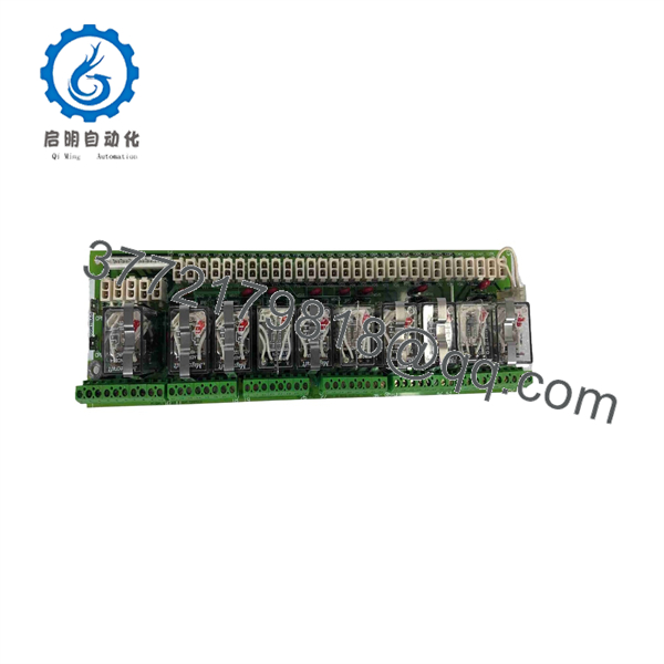
DS200RTBAG3AFB
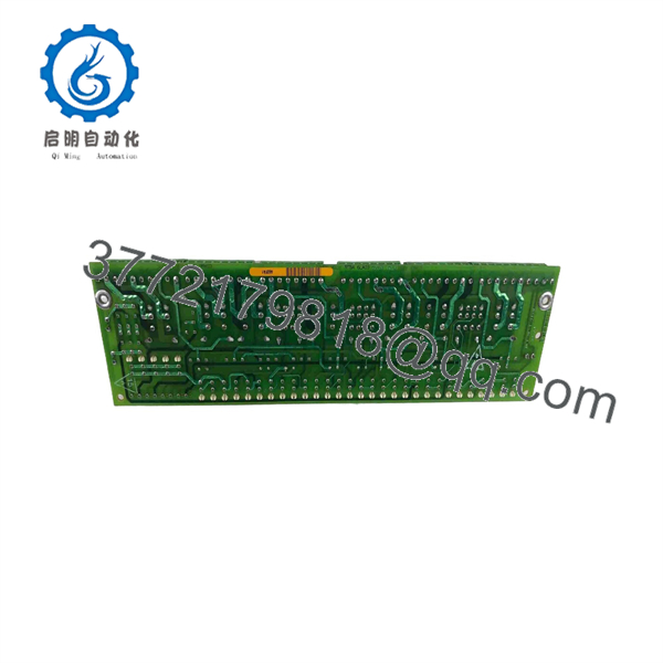
DS200RTBAG3AFB
Frequently Asked Questions
What is the GE ?
The is a General Electric RTBA relay terminal board for a Mark V Speedtronic turbine-control system. It provides relay-based discrete interfaces between the control system and turbine field circuits.
How many relays are on ?
Available technical references identify ten relays, located at K20 through K29. They report seven 10 A DPDT relays at K20–K26 and three 1 A 4PDT relays at K27–K29. Verify the relay configuration from the actual unit and approved GE documentation before applying these ratings to a field circuit.
What relay coil voltage does use?
Aftermarket references identify 115 V AC relay coils for this RTBA board. Confirm the coil-voltage marking and installed jumper configuration from the physical board before replacement or testing.
Is interchangeable with DS200RTBAG3A?
Not automatically. DS200RTBAG3A may be used as a broader board-family reference, while identifies a specific revision or configuration. Match the full orderable part number, board group, relay layout, connectors, jumper configuration, and Mark V system drawings.
Is this board used in GE Mark V turbine controls?
Yes. Available sources identify the RTBA board as Mark V turbine-control hardware. Mark V applications can include gas and steam turbine control systems, where discrete relay outputs interface to field devices and turbine-protection functions.
Can I hot-swap ?
Do not assume hot swapping is permitted. This board carries field interface wiring and may control active turbine circuits. Place the turbine system in the approved maintenance state, follow lockout/tagout and turbine OEM procedures, isolate the applicable energy sources, document jumper settings, and perform the required post-installation checks.
Will replacing erase Mark V turbine-control logic?
The Mark V application logic normally resides in the control system, not in this relay terminal board. However, a board replacement can still cause a trip, an incorrect field output, or a configuration fault if jumpers, connectors, terminal wiring, or board revision do not match. Always perform the approved functional and trip-path verification before returning equipment to operation.
Why is a New Surplus cheaper than OEM supply?
New Surplus boards commonly originate from unused turbine-spare inventory, plant upgrades, canceled projects, distributor stock, and decommissioned Mark V systems. Lower price does not establish authenticity, revision compatibility, storage conditions, or suitability for a turbine safety application. Request exact-board photos, label confirmation, relay and terminal condition images, jumper photographs, serial or traceability information where available, written warranty terms, and a test record.
What testing should a supplier perform before shipping a refurbished board?
Request inspection for corrosion, damaged terminals, burned relay contacts, cracked solder joints, damaged MOVs, rework marks, and connector damage; label and revision documentation; controlled relay-coil energization; contact-transfer verification for all ten relays; contact-resistance checks; terminal continuity checks; and a documented test report. A supplier test does not replace site loop checks, Mark V diagnostics, trip-path testing, and turbine OEM commissioning procedures.



