
 WhatsApp: +86 16626708626
 Email:
  Phone: +86 16626708626
Description
3. Key Technical Specifications
| Parameter | Value |
|---|---|
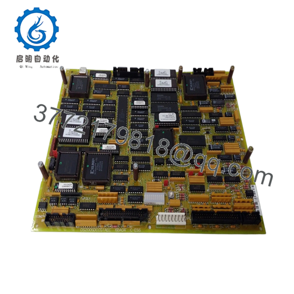
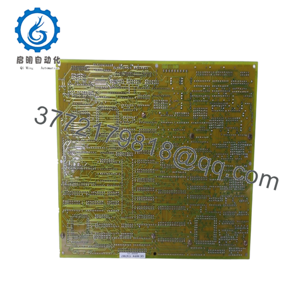
| Model Number | DS200SDCCG1AEC |
| Manufacturer | GE General Electric |
| Product Type | Drive Control Card |
| Series | GE Mark V Speedtronic |
| Functional Acronym | SDCC |
| Controller Architecture | Three microprocessors with shared RAM |
| Diagnostic Indicators | Ten onboard LEDs |
| Compatible Auxiliary Boards | SLCC, LCC, SPC, PSCB |
| Instruction Manual | GEI-100029 |
| PCB Coating | Normal coating |
| Functional Revision 1 | A |
| Functional Revision 2 | E |
| Artwork Revision | C |
| Installation Type | Mark V rack/control cabinet |
| Product Status | Legacy / Discontinued |
The DS200SDCCG1AEC acts as the primary controller card for GE Mark V automated drive systems and includes three microprocessors with shared RAM access capability. The board also uses ten diagnostic LEDs and supports multiple auxiliary boards.
4. Product Introduction
The GE DS200SDCCG1AEC is a Drive Control Card used in GE Mark V Speedtronic systems for steam, gas, and industrial drive applications. It functions as the primary drive controller and handles processing tasks across connected control and interface hardware.
In field deployments of Mark V systems, the SDCC board effectively acts as the control center of the drive section. Plants usually stock spare units because board failure can take an entire drive train offline, and exact revision matching becomes difficult as inventory ages. The AEC suffix matters. Treat it as a compatibility requirement, not a cosmetic revision.

- DS200SDCCG1AEC
- DS200SDCCG1AEC
5. Installation & Configuration Guide
Stage 1: Pre-Installation Preparation (Estimated Time: 10 minutes)
⚠️ Safety First: Notify operations of scheduled downtime. Confirm process safe state. Apply lock out/tag out procedures and wait at least 5 minutes for discharge of cabinet capacitors.
Tools Required
- ESD wrist strap
- PH1 screwdriver
- Fluke 115 multimeter
- Wire labels
- Smartphone for photos
- Flashlight
Data Backup
- Export drive parameters and controller data.
- Record fault history.
- Photograph all connectors.
- Photograph jumper locations.
- Record revision labels.
⚠️ Mark V cabinets often contain modifications from previous shutdowns. Never assume field wiring matches old documentation.
Stage 2: Removing the Old Module (Estimated Time: 5–10 minutes)
Steps:
- Remove cabinet access panels.
- Label all connectors before removal.
- Disconnect wiring carefully.
- Release retaining hardware.
- Pull the board straight outward.
Inspect:
- Bent pins
- Dust buildup
- Corrosion
- Connector wear
- Heat damage
⚠️ Keep the old board nearby.
I’ve watched technicians throw failed boards into a spare box and later realize they forgot to document a jumper arrangement.
Stage 3: Installing the New Module (Estimated Time: 5 minutes)
Steps:
- Wear grounded ESD protection.
- Verify exact model DS200SDCCG1AEC.
- Configuration Clone (Crucial): Match every jumper and hardware setting.
- Install board evenly.
- Confirm complete seating.
- Reconnect cables.
Self-Checklist:
- Jumpers match
- Wiring secure
- Board fully seated
- Retainers locked
❗This is the most common rookie mistake, but experienced engineers do it too. Take a picture before removal.
Stage 4: Power-On & Testing (Estimated Time: 10–15 minutes)
Pre-Power Check
Use a multimeter and verify no short exists on the 24 V rail.
Power-up procedure:
- Energize rack only.
- Observe startup LEDs.
- Verify LED sequence.
- Connect engineering workstation.
- Check communication and diagnostics.
- Run dry I/O testing.
LED behavior:
- Sequential flashing LEDs: Board operating normally
- Slow flash: Faults 1–399
- Fast flash: Faults 400–1023
The SDCC board uses ten diagnostic LEDs and different blink rates to indicate fault ranges.
⚠️ Troubleshooting Note: Solid faults immediately after installation often indicate revision mismatch or incorrect jumper settings.
I’ve seen a replacement consume two shifts because firmware moved from V2.x hardware to later revisions. The board fit physically. Communications did not.
6. Frequently Asked Questions (FAQ)
Q1. Can I hot-swap this module?
No.
Do not hot-swap the DS200SDCCG1AEC. Removing the board under power risks backplane damage and unpredictable controller faults.
Kill power first.
Q2. Is DS200SDCCG1AEC obsolete?
Yes.
The board belongs to GE’s legacy Mark V family. Current inventory usually comes from surplus warehouses or refurbished tested units because OEM production has ended.
Q3. Does the AEC suffix matter?
Absolutely.
The AEC suffix identifies functional and artwork revisions. GE revision changes sometimes alter timing behavior, jumper assignments, or hardware interaction.
I have seen technicians swap “close enough” revisions and spend two days chasing communication timeout alarms.
Q4. Will I lose programming logic when removing this board?
Usually no, but verify first.
The SDCC primarily serves as a drive controller board. Application logic often resides elsewhere in the Mark V architecture. Still, back up everything.
Assumptions create expensive outages.
Q5. How do I reset the board?
Several reset methods exist:
- Front-panel RESET pushbutton
- External +5 to +24 VDC reset trigger
- Software-triggered reset
- Internal watchdog reset circuitry
GE documentation identifies multiple reset mechanisms depending on system architecture.
Q6. How are these boards tested before shipment?
Standard workflow:
Inbound Inspection & Traceability
- Source verification
- Serial inspection
- Anti-counterfeit checks
- Corrosion inspection
- Visual review for rework marks
Live Functional Testing
- Tested on compatible GE hardware where available
- Power-up verification
- LED diagnostic verification
- Communication testing
- Simulated I/O operation
- Continuous operation >24 hours
Electrical Testing
- 500 V insulation resistance testing (>10 MΩ)
- Ground continuity verification
- Hipot testing if required
Firmware & Configuration Verification
- Revision recording
- Jumper documentation
Final QC
- Inspector sign-off
- ESD packaging
- Bubble wrap protection
- Heavy-duty corrugated shipping box
Test photos and videos are available upon request.
Q7. What installation mistake causes the most downtime?
❗Jumper settings and revision mismatches.
This board contains configurable hardware using JP and WJ jumpers. Pull a board without documenting those settings and you’re creating your own troubleshooting project. GE documentation specifically identifies configurable jumper hardware on this model.
Keep these checks in mind and you’ll save yourself 90% of typical rework time.


