
 WhatsApp: +86 16626708626
 Email:
  Phone: +86 16626708626
Description
3. Key Technical Specifications
| Parameter | Value |
|---|---|
| Manufacturer | GE General Electric |
| Model Number | DS200SDCCG4A |
| Functional Acronym | SDCC |
| Product Type | Drive Control Card |
| Platform | GE Mark V Speedtronic |
| Primary Application | TC2000 turbine control systems |
| Processor Architecture | Triple 16-bit microprocessors |
| Drive Control Processor | Intel 80C186 |
| Motor Control Processor | Intel 80C196 |
| Co-Motor Processor | TMS320C25 DSP |
| Memory Configuration | 4 EPROM + 1 EEPROM |
| Memory Access | Dual-port RAM architecture |
| Diagnostic LEDs | 10 onboard fault/status LEDs |
| Reset Methods | Pushbutton, watchdog, software, external |
| Operating Voltage | +5 VDC, ±15 VDC, ±24 VDC |
| Mounting Location | Mark V C Core |
| Communication Interfaces | 1PL, 2PL, 3PL, 6PL, 7PL, 8PL, 11PL |
| Operating Temperature | 0 °C to 60 °C |
| Storage Temperature | −40 °C to +85 °C |
| PCB Coating | Standard industrial coating |
| Compatibility | TC2000 turbine firmware applications |
4. Product Introduction
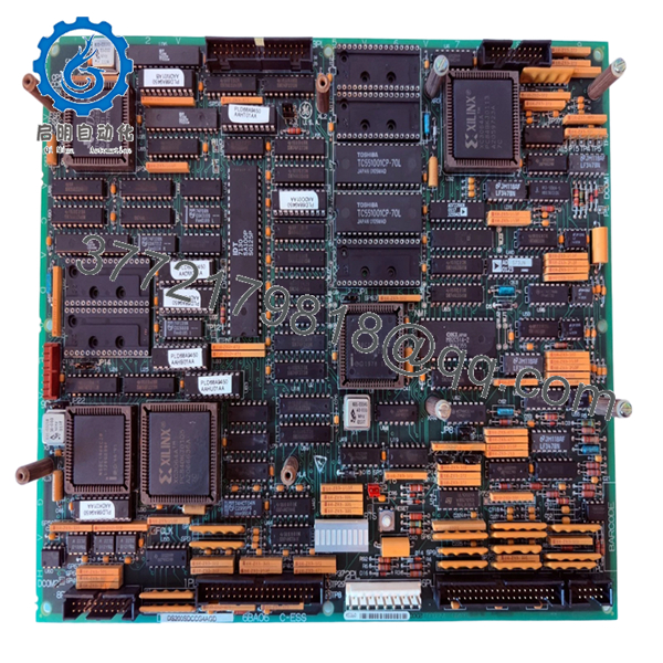
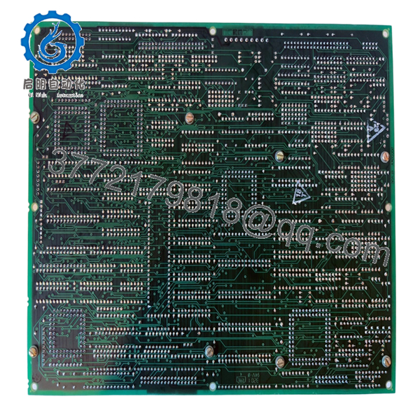
The GE DS200SDCCG4A is a Mark V Speedtronic drive control card used as the primary processing board in TC2000 turbine control systems. Installed in the C Core section of the Mark V panel, it coordinates turbine control logic, I/O handling, overspeed protection, and drive management functions.
In field deployments, this board is commonly retained during long-term lifecycle support projects because it preserves the original Mark V architecture, EPROM configuration, and turbine-specific firmware environment. Plants running mature gas turbine fleets often keep tested SDCC spare inventory onsite specifically to avoid extended outage exposure.

- DS200SDCCG4A
- DS200SDCCG4A
5. Installation & Configuration Guide
Stage 1: Pre-Installation Preparation (Estimated Time: 15 Minutes)
⚠️ Safety First
- Coordinate maintenance activity with turbine operations and electrical teams.
- Bring the turbine and associated drive systems into a verified safe shutdown state.
- Lock out/tag out all cabinet AC and DC feeds.
- Wait at least 10 minutes for internal DC bus and rack capacitors to discharge.
❗Do not assume the panel is safe because the HMI is dark. I’ve measured over 300 VDC still sitting on Mark V drive sections long after shutdown.
Tools Required
- Grounded ESD wrist strap
- PH1 screwdriver
- Fluke 115 multimeter or equivalent
- Wire labels
- Smartphone for connector photos
- Flashlight for cabinet inspection
Data Backup
- Backup all Mark V configuration and turbine parameter files.
- Record:
- Firmware revisions
- EPROM identifiers
- Rack slot location
- Existing fault codes
- Photograph:
- Connector routing
- Jumper positions
- Adjacent boards
- Ribbon cable orientation
❗Take detailed pictures before removing the board. The SDCC interfaces with multiple adjacent boards through tightly packed connectors. One shifted ribbon cable can create intermittent faults that waste an entire startup shift.
Stage 2: Removing the Old Module (Estimated Time: 10 Minutes)
- Remove cabinet covers carefully.
- Label all connectors before disconnecting.
- Disconnect ribbon cables and plugs evenly without flexing the PCB.
- Release retaining clips or mounting hardware.
- Pull the board straight out from the rack guides.
Inspection Checklist
- Inspect connectors for heat discoloration
- Check for damaged EPROM sockets
- Look for capacitor swelling
- Verify no bent backplane pins
- Remove conductive dust buildup carefully
⚠️ Note
Keep the original board available during commissioning. Even failed SDCC cards are useful for confirming jumper settings and EPROM orientation.
Stage 3: Installing the New Module (Estimated Time: 10–15 Minutes)
- Wear the ESD strap before opening the anti-static packaging.
- Verify exact model number: DS200SDCCG4A.
- Confirm firmware and EPROM compatibility.
Configuration Clone (Crucial)
- Match all jumper settings exactly.
- Verify EPROM locations and orientation.
- Confirm turbine-specific firmware compatibility.
❗This is one of the most expensive mistakes in Mark V maintenance. I’ve seen engineers install the correct hardware with the wrong EPROM set and spend two days troubleshooting phantom overspeed and startup permissive faults.
Installation Steps
- Align the board carefully with the rack guides.
- Insert evenly until fully seated.
- Secure retaining hardware properly.
- Reconnect all ribbon cables and communication connectors.
Self-Checklist
- Model verified
- EPROM orientation confirmed
- Jumpers duplicated
- Connectors fully seated
- Board locked securely
Stage 4: Power-On & Testing (Estimated Time: 20–30 Minutes)
Pre-Power Check
- Use a multimeter to verify no shorts exist on power rails.
- Check cabinet grounding continuity.
- Confirm ribbon cable alignment carefully.
Power-On Procedure
- Energize the Mark V rack only.
- Observe diagnostic LEDs during startup.
- Verify:
- Proper initialization
- No watchdog faults
- Stable processor activity
- Communication with associated boards
- Connect the engineering workstation.
- Confirm:
- Firmware recognition
- EEPROM parameter integrity
- No processor mismatch alarms
- Perform dry-run turbine permissive testing before enabling field devices.
⚠️ Troubleshooting Notes
- Continuous watchdog resets: Suspect EPROM mismatch or corrupted firmware.
- No communication with adjacent boards: Check ribbon cable seating and connector orientation.
- Random turbine faults after startup: Verify EEPROM parameter integrity.
I’ve watched technicians replace power supplies, I/O boards, and signal processors when the real issue was one improperly seated SDCC ribbon connector.
Technical Pitfalls & Survival Guide
❗ Firmware Revision Mismatch
This is the number one Mark V startup killer.
Before replacement:
- Record EPROM labels
- Verify firmware compatibility
- Confirm TC2000 application version
I once worked a turbine outage where the replacement SDCC physically fit perfectly but carried the wrong TC2000 firmware revision. The unit booted, then refused synchronization during startup checks.
❗ EPROM Handling Errors
EPROM chips are easy to damage or misinstall.
Always:
- Note orientation notch direction
- Avoid bending pins
- Use ESD protection
- Verify chip seating carefully
One reversed EPROM can stop the entire Mark V core from booting.
❗ Ribbon Cable Misalignment
This happens constantly during rushed outages.
Before removal:
- Photograph every connector
- Label ribbon cables clearly
- Verify pin alignment manually
Never force ribbon connectors.
❗ Power Supply Stability
The SDCC depends heavily on stable rack voltages.
Verify:
- +5 VDC rail stability
- ±15 V rails
- Cabinet cooling airflow
I’ve seen unstable ±15 V rails create random processor resets that looked exactly like firmware corruption.
❗ Electrostatic Discharge (ESD)
These processor boards are extremely static-sensitive.
Use:
- Grounded wrist strap
- ESD-safe work surface
- Anti-static packaging
I once watched a contractor unpack an SDCC board on cardboard during winter maintenance season. The board powered up once, then never booted again.
Keep these checks in mind and you’ll save yourself 90% of typical rework time.
6. Frequently Asked Questions (FAQ)
Q1: Can I hot-swap the GE DS200SDCCG4A?
No. This board functions as the primary control processor inside the Mark V core. Removing it under power can crash the entire turbine control system and potentially corrupt memory or damage connected boards.
Q2: What is the main difference between the G1A and G4A versions?
The G4A revision was developed specifically for TC2000 turbine applications. It includes expanded EEPROM storage and turbine-specific firmware behavior compared to the standard G1A drive-control variant.
Q3: Is the DS200SDCCG4A obsolete?
Yes. The Mark V platform is legacy GE hardware. Most available inventory now comes from surplus OEM stock, plant decommissioning projects, or specialty industrial automation suppliers.
Plants with mature turbine fleets still actively maintain spare SDCC inventory because a failed controller board can extend outages significantly.
Q4: Does this board include EPROM chips?
Not always.
Some replacement boards ship:
- Fully populated with EPROMs
- Without memory chips
- With generic firmware only
Always verify:
- EPROM inclusion
- Firmware revision
- TC2000 compatibility
This matters more than many buyers realize.
Q5: What is the most common installation mistake?
EPROM and ribbon cable mistakes.
Honestly, this causes more startup delays than failed hardware:
- One shifted ribbon connector
- Incorrect EPROM orientation
- Wrong firmware revision
- Loose socket seating
The panel may partially boot while hiding processor communication failures underneath.
Q6: Why are some DS200SDCCG4A boards much cheaper online?
Testing and traceability standards vary heavily in the surplus controls market.
Lower-priced boards may:
- Lack verified EPROMs
- Skip load testing
- Have unknown storage history
- Include repaired assemblies
- Omit firmware validation
Always ask for:
- EPROM photos
- Test reports
- Startup verification
- PCB inspection images
Q7: What testing is typically performed before shipment?
Typical QC procedures include:
- Inbound Inspection & Traceability
- OEM label verification
- Serial number inspection
- EPROM verification
- Anti-counterfeit inspection
- Functional Testing
- Installed into compatible Mark V test rack
- Power-on diagnostics
- Processor communication verification
- LED fault testing
- Watchdog validation
- Electrical Testing
- Ground continuity checks
- Insulation resistance testing
- Power rail verification
- Firmware & Configuration Verification
- EPROM identification
- Firmware revision recording
- Jumper documentation
- Final QC & Packaging
- QC sign-off
- ESD bag sealing
- Heavy-duty export carton packaging
- QC date labeling
Test photos and startup videos are available upon request.


