
 WhatsApp: +86 16626708626
 Email:
  Phone: +86 16626708626
Description
3. Key Technical Specifications
| Parameter | Specification |
| Manufacturer | General Electric (GE) |
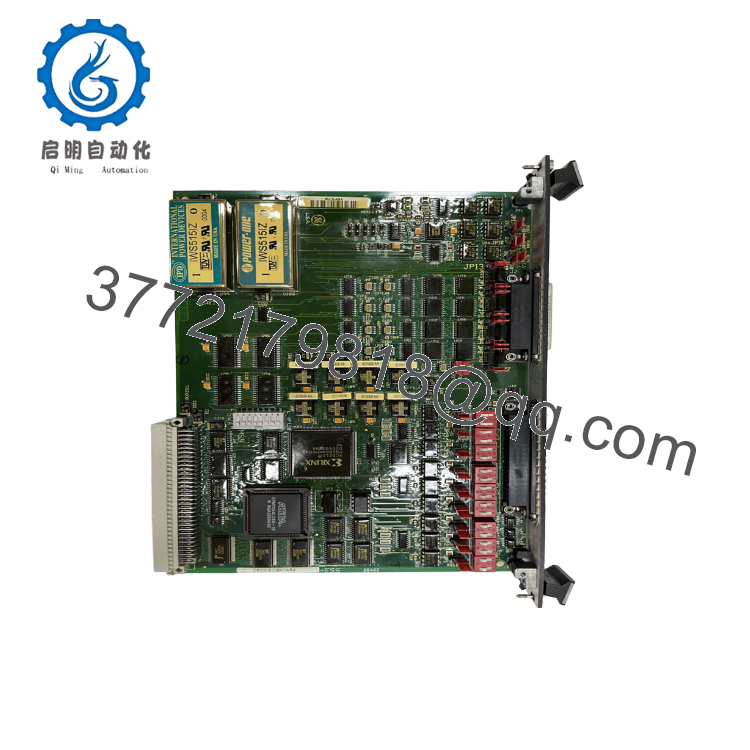
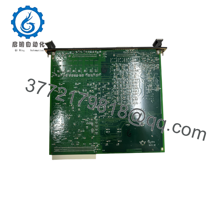
| Part Number | DS200SIOBH1ABA |
| Series Compatibility | Speedtronic Mark V Series |
| Functional Acronym | SIOB (VME Stand I/O Board) |
| Bus Interface Standard | VME Standard P1 Connector (occupies 1 full VME slot) |
| Onboard Hardware | 20x Configurable Jumpers | 3x DIP Switch Blocks (18 physical poles total) |
| External Connectors | 1x 40-pin header (to TCQA/TCQC terminal boards) | 3PL interface to STCA |
| Status Indicators | 1x Faceplate Diagnostic LED (illuminates upon VME bus access) |
| Assembly Type | Normal Assembly |
| PCB Protection | Industrial Conformal Coating (moisture and particulate protection) |
| Operating Temperature | -40 to +70 °C |
| Voltage Input | 24 Vdc / 48 Vdc nominal configuration |
| Power Consumption | Approximately 5 W at 24 Vdc |
| Isolation Rating | 1,500 Vac field-to-logic isolation |
4. Product Introduction & Supply Chain Strategy
The GE DS200SIOBH1ABA is a high-performance VME Stand I/O (SIOB) control card designed for the Speedtronic Mark V turbine control system platform. This card acts as a specialized hardware bridge between field instruments and the VME processor, processing analog signals (such as 4–20 mA, LVDTs, thermocouples, and vibration sensors) and delivering actuator-level drive signals back to servo valves and gas turbine fuel control loops. It slides directly into standard Mark V VME slots to expand the system’s physical signal-handling capacity with high precision and low latency.
From a procurement perspective, the DS200SIOBH1ABA is a discontinued, legacy component. Relying on refurbished boards is a significant gamble; field-side input circuits are constantly exposed to high electrical transients, meaning used units often suffer from degraded isolation barriers and weakened signal filtering circuits. Acquiring a verified New Surplus board provides a highly reliable insurance policy against costly industrial downtime, preserving factory-original performance and keeping critical turbine or drive networks fully operational.

- DS200SIOBH1ABA
- DS200SIOBH1ABA
5. Installation & Configuration Guide
Stage 1: Pre-Installation (Prep & Safety)
- System De-energization: Power down the target VME rack assembly. Tag and lock out the primary power feed. Verify zero voltage across adjacent field terminal lines using a digital multimeter.
- ESD Mitigation: Wear a properly grounded ESD wrist strap throughout the replacement process. Static discharges can easily damage sensitive logic gates on the VME interface.
- Visual Documentation: Document and photograph the physical locations of all 20 jumpers and the exact positions of the 18 poles across the three onboard DIP switch blocks.
Stage 2: Removal
- Disconnect Cables: Unplug the 40-pin connector and auxiliary ribbon cables (3PL/JE) connected to the board faceplate or front surface.
- Card Extraction: Loosen the upper and lower faceplate retaining screws. Grasp the card using the board injector/ejector tabs and pull it smoothly outward along the VME card guides, avoiding any twisting motion that might damage the backplane pins.
- Storage: Lay the extracted card flat on an ESD-safe conductive mat.
Stage 3: Installation (Clone & Seat)
- Jumper Configuration: Set all 20 jumpers on the new DS200SIOBH1ABA board to mirror the exact configuration of the old board.
- DIP Switch Matching: Align the 18 switches across the three DIP blocks to replicate the exact open/closed positions of the old card.
- Card Seating: Align the board with the slot rails of the VME rack. Gently slide it in until the rear P1 connector meets the backplane socket. Apply firm, even pressure using the ejector handles to fully seat the board. Secure the faceplate screws.
- Cable Connection: Firmly reconnect all interface cables, ensuring correct alignment and robust physical latching.
Stage 4: Power-On & Testing
- Cold Resistance Check: Perform a quick continuity check on the field-side supply inputs to ensure no physical ground faults were introduced during connection.
- Power Application: Power up the VME rack control bus.
- Status Monitoring: Observe the faceplate diagnostic LED. It should illuminate or flicker during startup, indicating that the active VME controller is successfully addressing and communicating with the SIOB board.
6. Firmware/Software Versions & Upgrade Notes
The DS200SIOBH1ABA operates purely as a hardware-level VME interface board and does not feature on-board flash memory or field-upgradable processor firmware. Hardware compatibility is instead determined by physical circuit board artwork revisions.
Ensure the functional revision codes (specifically the H1ABA suffix) align with the requirements of your main drive control card (such as the DS200SDCC) or core processor module. Substituting an earlier revision board with a newer ABA card usually does not require system-level software re-flashing, but all field terminal parameters on the interface card must be carefully mapped. Mixing older, unshielded terminal setups with newer, conformal-coated modules without verifying signal ground configurations can introduce noise into analog loop channels.
7. Frequently Asked Questions (FAQ)
- Are these DS200SIOBH1ABA cards used or pulled from decommissioned systems? No, this module is a genuine New Surplus unit. It has never been installed or run in a live industrial system. While it is a legacy GE Mark V component, it has been stored in climate-controlled environments and remains in unused, factory-sealed condition inside its original anti-static packaging.
- What is the significance of the “SIOB” functional acronym? SIOB stands for VME Stand Input/Output Board. It defines the card’s fundamental role: acquiring external signal measurements (voltage, current, and sensor telemetry) and converting them into standardized data formats that can be processed directly over the Mark V VME controller backplane.
- Why is there such a large price difference between New Surplus and refurbished options? A refurbished module is a used card that has undergone basic cleaning and simple diagnostic tests. It carries the risk of component wear and latent thermal stress. A New Surplus card represents “zero-hour” OEM reliability, with brand-new silicon, fresh conformal coating, and zero degradation in its isolation circuitry. It represents the lowest Total Cost of Ownership (TCO) for plants prioritizing reliability.
- Does this card support hot-swapping inside a live VME rack? No. Swapping this card while the VME backplane or the associated turbine control system is energized is highly dangerous. It can corrupt data transmissions on the VME bus and generate voltage spikes that damage adjacent processor modules. Always shut down power before servicing the rack.
- What do the onboard DIP switches control? The three switch blocks (containing 18 switches total) configure physical hardware options on the card. This includes setting signal path gains, selecting analog input ranges, and configuring physical address parameters on the VME bus structure. These must be matched exactly to your old board’s configuration to ensure proper operation.



