
 WhatsApp: +86 16626708626
 Email:
  Phone: +86 16626708626
Description
3. Key Technical Specifications
| Parameter | Value |
|---|---|
| Manufacturer | General Electric |
| Model | DS200TCCBG1BED |
| Functional Acronym | TCCB |
| Product Type | Common Extended Analog I/O Board |
| Series | Mark V Speedtronic |
| Power Requirement | +5 V DC |
| Processor | Intel 80196 Microprocessor |
| Memory | Multiple PROM modules |
| Connectors | JCC and JDD (50-pin) |
| Signal Types | 4–20 mA, 0–1 mA, RTD, PT/CT |
| PCB Coating | Normal coating |
| Functional Revision | B/E with D artwork revision |
| LED Indicators | Single board-mounted LED |
| Manual Reference | GEH-6153 |
| Product Status | Legacy / Obsolete |
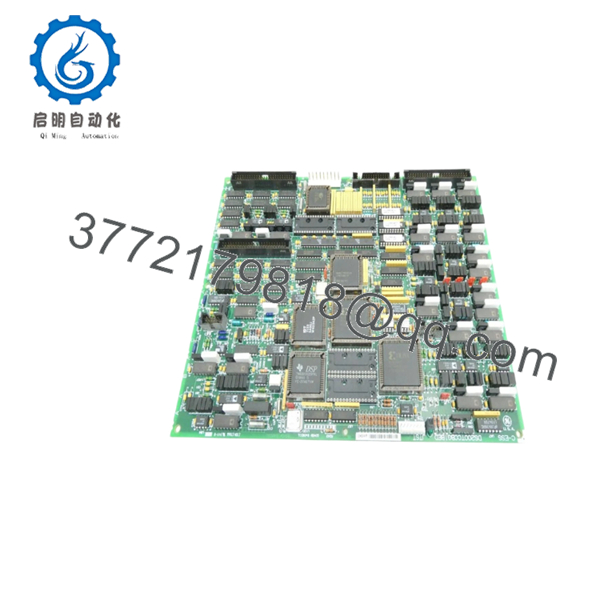
The DS200TCCBG1BED serves as a Common Extended Analog I/O Board in GE Mark V systems. It processes and conditions analog signals from terminal boards before passing data into turbine control logic. The board includes an Intel 80196 processor and uses removable PROM modules for firmware storage.
4. Product Introduction
GE DS200TCCBG1BED is an Extended Analog I/O Board designed for GE Mark V Speedtronic turbine control systems. It accepts analog and RTD signal inputs, conditions the data, and transfers processed information into control architecture used in power generation and industrial drive applications.
In field deployments of older Mark V systems, these boards often remain operational for twenty years or longer. Most plants replace the board itself rather than redesign analog signal architecture because cabinet modifications and logic validation usually cost more than the hardware swap.
- DS200TCCBG1BED
5. Installation & Configuration Guide
Stage 1: Pre-Installation Preparation (Estimated: 10 minutes)
⚠️ Safety First: Notify operations of downtime. Confirm equipment shutdown. Apply lockout/tagout procedures and isolate cabinet power. Wait at least 5 minutes for capacitor discharge.
Tools Required
- ESD wrist strap
- PH1 screwdriver
- Fluke 115 multimeter
- Wire labels
- Smartphone for photos
- Flashlight
Data Backup
- Export system configuration files.
- Record rack and slot position.
- Photograph all wiring and ribbon cables.
- Photograph jumper positions.
- Record PROM module locations.
I’ve seen maintenance teams skip PROM documentation because “it only fits one way.”
Then someone rotates a module during installation.
Now the board does not boot.
Stage 2: Removing the Old Module (Estimated: 5–10 minutes)
- Remove cabinet access covers.
- Label every connector.
- Disconnect ribbon cables carefully.
- Release retention hardware.
- Pull board straight outward.
⚠️ Do not tilt the board during removal.
Mark V backplane connectors are tougher than they look, but one bent pin creates intermittent faults that only show up under load.
Inspect:
- Bent pins
- Dust contamination
- Heat discoloration
- Connector oxidation
- Damaged sockets
⚠️ Keep the old board nearby until startup verification finishes.
Stage 3: Installing the New Module (Estimated: 10 minutes)
- Wear ESD protection.
- Verify DS200TCCBG1BED exactly matches.
- Configuration Clone (Crucial): Copy all PROM modules, jumpers, and hardware settings.
- Install board evenly.
- Confirm seating.
- Reconnect all wiring.
Self-check:
- PROM modules transferred correctly
- Jumpers match
- Wiring secure
- Board seated completely
❗Take photographs before removing the old board.
This is the most common mistake I still see.
Stage 4: Power-On & Testing (Estimated: 10–15 minutes)
Pre-Power Check
Use a multimeter and verify no short exists on control power rails.
Power-up steps:
- Energize control rack only.
- Observe board LED status.
- Connect engineering software.
- Verify analog channels.
- Check RTD readings.
- Run dry I/O simulation.
⚠️ Troubleshooting Note: If communication or analog channel faults appear immediately, inspect PROM transfer and revision compatibility before replacing additional hardware.
I watched a site troubleshoot a “failed analog board” for a day and a half.
Someone forgot to transfer one PROM.
Quality Verification SOP
1. Inbound Inspection & Traceability
- OEM package review
- Serial verification
- Anti-counterfeit checks
- Visual inspection for corrosion, scratches, UV yellowing, and repair marks
- Accessory verification
2. Live Functional Testing
Test environment:
- Genuine GE Mark V rack or equivalent simulator
Procedure:
- Power-on self-test
- LED verification
- Communication handshake testing
- Analog signal simulation
- Continuous operation exceeding 24 hours with thermal monitoring
Official test reports generated.
3. Electrical Parameter Testing
- 500 V Megger insulation test (>10 MΩ)
- Ground continuity check
- Hipot testing where applicable
4. Firmware & Configuration Verification
- Firmware revision recording
- PROM documentation
- Jumper photography
5. Final QC & Packaging
- QC inspector sign-off
- Anti-static ESD packaging
- Bubble protection
- Heavy-duty corrugated packaging
- QC inspection labels
Test videos and photos available upon request.
Technical Pitfall & Survival Guide
❗ Firmware Revision Mismatch
Document revision numbers before removal.
I once saw a replacement board generate communication alarms for two days.
Everything matched except revision levels.
❗ PROM Transfer Errors
This catches people constantly.
DS200TCCBG1BED processing depends on PROM hardware.
Miss one module and troubleshooting starts immediately.
❗ Terminal and Connector Assumptions
Connector locations may appear identical across revisions.
Verify drawings.
Do not trust memory.
❗ Power Supply Assumptions
Leave a 20% spare capacity margin.
Additional analog boards quietly consume cabinet power reserves.
❗ Electrostatic Discharge
I watched an engineer install a board during dry winter weather with no wrist strap.
Powered up.
Instant smoke.
That lesson cost several thousand dollars.
Keep these checks in mind and you’ll save yourself 90% of typical rework time.
6. Frequently Asked Questions (FAQ)
Q1: Can I hot-swap this module?
No.
Mark V systems were not intended for live insertion of analog boards. Pulling the board under power can interrupt signal processing and damage connectors.
Power down first.
Q2: Is DS200TCCBG1BED obsolete?
Yes.
GE discontinued active production years ago. Inventory generally comes from New Surplus stock or tested refurbished inventory.
Q3: Do I need to transfer PROM modules?
Yes.
This board stores processing instructions on PROM modules. During replacement, transfer the existing PROM modules unless replacement documentation states otherwise.
Q4: Will I lose programming when replacing the board?
Normally no.
Application logic typically remains elsewhere in the Mark V architecture.
Still perform backups.
I have never regretted making one.
Q5: Why is surplus inventory cheaper than OEM pricing?
You are generally purchasing plant spare inventory or tested secondary-market stock rather than factory production.
Availability drives pricing more than original list cost.
Q6: Is inventory genuinely new?
Sometimes.
“New Original” often means unused surplus stock stored after manufacturing ended.
Request actual photos before issuing a purchase order.
Q7: What warranty is typical?
Tested inventory commonly includes a 12-month warranty, although terms vary between suppliers and stock conditions.


