
 WhatsApp: +86 16626708626
 Email:
  Phone: +86 16626708626
Description
3. Key Technical Specifications
| Parameter | Value |
|---|---|
| Manufacturer | GE General Electric |
| Model | DS200TCDAG2BBA |
| Product Type | Digital Input/Output Board |
| Series | Mark V Speedtronic |
| Functional Acronym | TCDA |
| Application Core | Q11, Q21, Q51 Digital I/O cores |
| Communication | IONET via JX1/JX2 |
| Input Sources | DTBA and DTBB terminal boards |
| Output Targets | TCRA relay/solenoid boards |
| Processor | Onboard microprocessor |
| Diagnostic LEDs | 10 front LEDs + 1 side status LED |
| Hardware Configuration | 8 onboard jumpers |
| Connectors | JR, JQ, JO1, JO2, JP, JX1, JX2 |
| Operating Temperature | 0–60 °C |
| Approximate Weight | 0.9–1.1 kg |
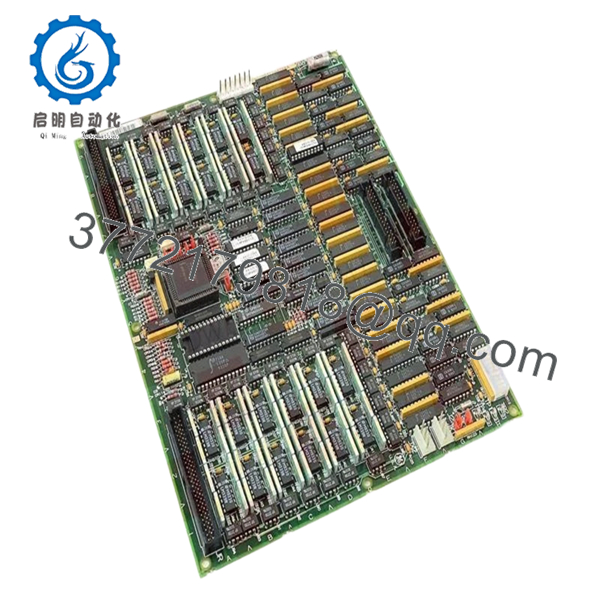
The DS200TCDAG2BBA board receives digital contact input signals and routes relay and solenoid output commands through the Mark V architecture using IONET communications.
4. Product Introduction
GE DS200TCDAG2BBA is a Mark V Digital Input/Output Board used inside GE Speedtronic turbine control systems. It processes digital contact inputs, relay outputs, and actuator signaling for turbine applications installed in Q11, Q21, and Q51 digital I/O cores.
In field deployments of Mark V systems, TCDA boards are frequently retained for decades because replacing the entire control layer usually creates more outage risk than maintaining the existing architecture. The board uses IONET communication and onboard signal processing to manage field contact data and actuator control.
5. Installation & Configuration Guide
Stage 1: Pre-Installation Preparation
Estimated Time: 10 minutes
⚠️ Safety First: Notify operations of planned downtime. Verify safe process state. Apply lockout/tagout. Wait a minimum of 5 minutes for capacitor discharge.
Tools Required
- ESD wrist strap
- PH1 screwdriver
- Fluke 115 multimeter
- Wire labels
- Smartphone for photos
Data Backup
- Export control logic and configuration files.
- Record IONET addressing information.
- Photograph all jumpers and ribbon cable routing.
- Photograph terminal connections and board location.
Stage 2: Removing the Old Module
Estimated Time: 5 minutes
- Remove front panel access.
- Label all ribbon cables and field connections.
- Disconnect cables carefully.
- Release board retention hardware.
- Pull module outward in a straight path.
- Inspect connector pins and backplane condition.
⚠️ Do not discard the old module during installation.
I have watched technicians lose two hours because they forgot original cable routing.
Stage 3: Installing the New Module
Estimated Time: 10 minutes
- Attach ESD protection.
- Verify DS200TCDAG2BBA revision and suffix match.
- Configuration Clone (Crucial): Replicate all jumper settings exactly.
- Verify J4, J5, and J6 IONET ID configuration.
- Verify J2 and J3 termination settings.
- Insert board evenly into guides.
- Reconnect cables and confirm seating.
Self-Checklist:
[ ] Jumpers match
[ ] Ribbon cable orientation correct
[ ] Tabs locked
❗This is the most common rookie mistake, but it happens constantly. Take a picture before you pull it. I can’t stress this enough.
Stage 4: Power-On & Testing
Estimated Time: 5 minutes
Pre-Power Check
Verify no shorts across supply rails using a Fluke 115 multimeter.
Power-Up Steps
- Energize rack power only.
- Observe LED startup sequence.
- Verify communication over IONET.
- Connect maintenance software.
- Verify board ID and hardware status.
- Dry-run digital input and relay output testing.
The board uses a sequence of diagnostic LEDs during normal operation and fault indication.
⚠️ Troubleshooting Note: If communication immediately fails after replacement, verify IONET addressing and jumper settings before replacing additional hardware.
Veteran Survival Guide — Technical Pitfalls
❗ Firmware Revision Mismatch
I’ve seen projects where a replacement module appeared physically identical but a revision difference caused intermittent communication faults for two shifts. Record the original suffix before removal.
❗ DIP Switch / Jumper Misconfiguration
Eight jumpers exist on this board.
Some configure IONET addressing. Others control termination and stall timer settings.
Miss one setting and you’ll chase faults all day. Take pictures before removal.
❗ Terminal Block and Cable Routing Errors
The JR and JQ cable routing matters. Ribbon cable installation errors create strange intermittent behavior that can look like processor failures. Document routing before removal.
❗ Power Consumption Oversight
Always calculate rack loading and leave 20% capacity margin.
One more board can push an already stressed supply over the limit.
❗ ESD Damage
I watched an engineer handle a board without a strap during winter maintenance. Powered up the cabinet and immediately released smoke.
That mistake cost several thousand dollars.
Keep these checks in mind and you’ll save yourself 90% of typical rework time.
SOP Quality Transparency
1. Inbound Inspection & Traceability
- Verify OEM packaging records and customs documentation
- Inspect serial numbers and anti-counterfeit labels
- Inspect PCB surface for scratches, corrosion, UV discoloration, or repair marks
- Verify manuals and accessories
2. Live Functional Testing
Testing performed on genuine GE Mark V rack hardware where available.
Procedure:
- Power-on verification
- LED sequence checks
- Communication handshake verification
- Digital input simulation
- Relay output testing
- Continuous runtime testing over 24 hours with thermal monitoring
- Generate documented test report
Photos and test videos available upon request.
3. Electrical Parameter Testing
- Insulation resistance using 500 V Megger (>10 MΩ)
- Ground continuity verification
- Voltage checks with Fluke 115
- Hipot testing where applicable
4. Firmware & Configuration Verification
- Document board revision level
- Record jumper settings
- Photograph hardware configuration
5. Final QC & Packaging
- QC inspector sign-off
- Anti-static ESD packaging
- Bubble wrap protection
- Heavy-duty corrugated packaging
- QC inspection label with date
Verified fully functional under load testing.

- DS200TCDAG2BBA
6. Frequently Asked Questions (FAQ)
Q1: Can I hot-swap this module?
No.
Mark V systems were not designed around live insertion practices. Pulling the board under power can damage the backplane or generate IONET faults.
Power down first.
Q2: Is DS200TCDAG2BBA obsolete?
Yes.
Mark V hardware belongs to GE’s legacy turbine platform. New inventory generally comes from surplus procurement or specialized stock channels.
Q3: What is the direct replacement if stock runs out?
Replacement depends on cabinet architecture and revision history. Verify suffix compatibility before ordering. DS200TCDAG2B and DS200TCDAG2BBA hardware revisions should never be assumed interchangeable without documentation review.
Q4: Will I lose my programming logic when replacing this board?
Normally no.
DS200TCDAG2BBA is a Digital I/O board, not the primary control processor. Still back up everything. After enough 2 AM outages, you stop trusting assumptions.
Q5: Why are prices lower than OEM list pricing?
Most inventory today comes from surplus channels, canceled projects, or excess procurement stock rather than current production. Availability and condition drive pricing more than original list value.
Q6: Why are communication faults appearing after installation?
Start with jumper settings.
J4, J5, and J6 control IONET addressing. Incorrect settings frequently create communication failures that look like processor problems.
Q7: Are startup test reports available?
Yes.
Request communication test logs, startup photos, and load-test records before shipment. Documentation avoids surprises during planned outages.


