
 WhatsApp: +86 16626708626
 Email:
  Phone: +86 16626708626
Description
3. Key Technical Specifications
| Parameter | Value |
|---|---|
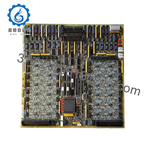
| Model Number | DS200TCDAH1BGD |
| Manufacturer | GE General Electric |
| Series | Speedtronic Mark V |
| Product Type | Digital I/O Distribution Board |
| Application | Gas and Steam Turbine Control |
| Mounting Method | Mark V Control Rack |
| Communication Interface | Proprietary Mark V Backplane |
| I/O Type | Digital Signal Interface |
| Operating Voltage | 24 V DC control environment |
| PCB Coating | Industrial conformal coating |
| Operating Temperature | 0 °C to +60 °C typical cabinet environment |
| Storage Temperature | −40 °C to +85 °C |
| Humidity Rating | 5% to 95% non-condensing |
| Firmware Dependency | Must match existing Mark V system revision |
| Condition | New Surplus / Tested Available |
| Country of Origin | USA |
4. Product Introduction
The GE DS200TCDAH1BGD is a Speedtronic Mark V digital I/O terminal board used in GE turbine control systems for gas and steam turbine applications. It handles digital signal distribution between field wiring and the Mark V control architecture.
In field deployments of Mark V systems, this board is commonly replaced during lifecycle extension projects where aging I/O hardware begins showing intermittent communication or terminal failures. Engineers typically select this revision when maintaining original rack compatibility and avoiding costly turbine control migrations.

- DS200TCDAH1BGD
- DS200TCDAH1BGD
5. Installation & Configuration Guide
Stage 1: Pre-Installation Preparation (Estimated Time: 10 Minutes)
⚠️ Safety First
- Notify operations and schedule turbine control downtime.
- Verify the turbine is in a safe shutdown state.
- Apply lockout/tagout procedures to all related control power sources.
- Wait at least 5 minutes for cabinet capacitors to discharge fully.
Tools Required
- ESD wrist strap
- PH1 screwdriver
- Fluke 115 multimeter
- Wire labels
- Smartphone for wiring photos
- Flashlight for rack inspection
Data Backup
- Export current Mark V configuration backups.
- Document all terminal assignments.
- Photograph every wiring connection before removal.
- Record cabinet slot location and any jumper settings.
❗This documentation step saves hours during troubleshooting. I have seen technicians skip photos, then spend half a shift tracing terminals one wire at a time.
Stage 2: Removing the Old Module (Estimated Time: 5–10 Minutes)
- Open the Mark V cabinet front access panel.
- Label all wiring before disconnecting terminals.
- Remove terminal plugs carefully. Do not pry against the PCB.
- Release rack retention hardware.
- Pull the board straight outward to avoid bending backplane connector pins.
- Inspect the rack connector for:
- Bent pins
- Dust buildup
- Carbon discoloration
- Loose terminal debris
⚠️ Note
Keep the old board nearby until startup is verified. Even failed boards are useful for jumper references and terminal confirmation.
Stage 3: Installing the New Module (Estimated Time: 10 Minutes)
- Wear the ESD strap before touching the PCB.
- Verify the exact model number: DS200TCDAH1BGD.
- Inspect the replacement board for shipping damage or cracked terminal blocks.
Configuration Clone (Crucial)
- Match all jumper and switch settings exactly to the original board.
- Verify terminal orientation carefully.
- Check grounding shield termination points.
❗This is the most common rookie mistake. Someone assumes “same board family” means identical settings. Then the turbine trips because the I/O addressing shifted.
- Insert the board evenly into the rack guides.
- Press firmly until fully seated.
- Tighten retaining hardware.
- Reconnect field wiring using proper torque.
Self-Checklist
- DIPs/jumpers verified
- Wiring secured
- Board fully seated
- Retention tabs locked
- No loose strands or shield shorts
Stage 4: Power-On & Testing (Estimated Time: 10–15 Minutes)
Pre-Power Check
- Use a multimeter to verify no short exists on the 24 V DC rail.
- Confirm cabinet grounding continuity.
Power-On Steps
- Energize the control rack only.
- Observe startup LEDs carefully:
- Green status LEDs: normal initialization
- Red fault LEDs: configuration or communication fault
- Connect the Mark V maintenance workstation.
- Verify:
- Rack communication
- Board recognition
- Alarm status
- I/O mapping
- Perform dry-run I/O simulation before enabling field devices.
- Verify all critical permissives and interlocks.
⚠️ Troubleshooting Note
- Solid fault LED after installation usually points to:
- Firmware mismatch
- Improper rack seating
- Incorrect jumper configuration
- No communication:
- Check backplane connector alignment
- Verify cabinet power supply voltage
- Confirm Mark V core revision compatibility
I have seen replacement projects stall for two days because someone mixed board revisions ending in different suffix letters. Always verify the exact suffix.
6. Frequently Asked Questions (FAQ)
Q1: Can I hot-swap the GE DS200TCDAH1BGD under power?
No. This board is not designed for hot-swapping in a live Mark V rack. Removing it under power can corrupt communication on the backplane or damage adjacent control cards. Shut down control power first.
Q2: Is the DS200TCDAH1BGD obsolete?
Yes. The GE Mark V platform is considered a legacy system. OEM production is limited, and most available inventory comes from surplus channels or specialized industrial stockholders.
That said, many power plants still operate Mark V systems reliably because turbine shutdown costs are much higher than maintaining legacy controls.
Q3: Is this genuinely new or refurbished?
This inventory is typically classified as New Original / New Surplus unless specifically marked refurbished. That means:
- Unused OEM hardware
- Long-term warehouse storage
- Original GE labeling typically intact
We recommend requesting:
- High-resolution photos
- Serial number verification
- Functional test reports
Test videos and startup verification photos are available upon request.
Q4: Will I lose my control logic if I replace this board?
Normally no. The DS200TCDAH1BGD functions as an I/O distribution/interface board rather than the primary logic storage device.
However, before touching any Mark V hardware:
- Back up the system configuration.
- Archive current control constants.
- Document cabinet addressing.
Never assume a 25-year-old turbine system still has recoverable backups.
Q5: What should I verify before ordering a replacement?
Three things:
- Exact model number including suffix letters
- Existing firmware/system revision
- Terminal compatibility
❗Even similar GE Mark V boards can differ internally between revisions. Ordering “close enough” hardware is how outages get extended.
Q6: Why is pricing lower than current OEM replacement systems?
Because this is legacy surplus inventory, not newly manufactured hardware. Plants maintaining Mark V systems often choose surplus replacement boards instead of migrating immediately to Mark VIe or another DCS platform.
A full migration can easily exceed six figures once engineering, commissioning, and downtime are included.
Q7: What testing is performed before shipment?
Typical QC procedure includes:
- Incoming visual inspection
- Anti-counterfeit verification
- PCB trace and solder inspection
- Power-on testing in a compatible Mark V test rack
- Communication handshake verification
- 24-hour thermal stability run
- Insulation resistance test using a 500 V Megger
- ESD-safe packaging and final QC signoff
We use genuine GE-compatible test racks and Fluke instrumentation during verification. Test reports can be supplied with shipment documentation.
Keep these checks in mind and you’ll save yourself 90% of typical rework time.


