
 WhatsApp: +86 16626708626
 Email:
  Phone: +86 16626708626
Description
3. Key Technical Specifications
| Parameter | Value |
|---|---|
| Model Number | DS200TCDAH1BHE |
| Manufacturer | GE General Electric |
| Series | Speedtronic Mark V DS200 |
| Functional Acronym | TCDA |
| Product Type | Digital I/O Board |
| Primary Application | Gas and Steam Turbine Control |
| System Compatibility | GE Mark V Control Systems |
| I/O Function | Digital contact input/output processing |
| Network Interface | IONET communication support |
| IONET Hardware | J2 and J3 termination resistors |
| IONET ID Configuration | J4, J5, J6 jumper settings |
| Digital Inputs | 32 contact inputs typical |
| Digital Outputs | 32 relay/solenoid outputs typical |
| Connectors | Two 50-pin connectors, two 3-pin connectors |
| Indicators | 1 side LED, 10-LED diagnostic block |
| Jumper Count | 8 configurable jumpers |
| Test Points | Integrated diagnostic test points |
| PCB Coating | Conformal-coated industrial PCB |
| Operating Temperature | 0 °C to +60 °C typical cabinet environment |
| Storage Temperature | −40 °C to +85 °C |
| Product Status | Legacy / Obsolete Hardware |
Technical details compiled from GE Mark V support documentation and field supplier references.
4. Product Introduction
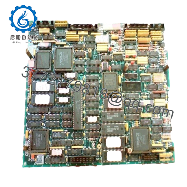
The GE DS200TCDAH1BHE is a Digital I/O Board used in GE Speedtronic Mark V turbine control systems for handling discrete input and output signal processing. It interfaces with DTBA, DTBB, TCRA, and TCQC assemblies through the Mark V IONET communication structure.
In field service environments, this board is commonly replaced during Mark V lifecycle maintenance projects where intermittent contact input faults, failed relay outputs, or unstable IONET communication begin affecting turbine startup reliability. Most facilities maintaining Mark V systems prefer direct hardware replacement to avoid extended migration outages.
5. Installation & Configuration Guide
Stage 1: Pre-Installation Preparation (Estimated Time: 10 Minutes)
⚠️ Safety First
- Notify operations before taking the turbine control cabinet offline.
- Verify the turbine is in a safe shutdown condition.
- Apply lockout/tagout procedures to all cabinet power feeds.
- Wait at least 5 minutes for capacitor discharge before touching hardware.
Tools Required
- ESD wrist strap
- PH1 screwdriver
- Fluke 115 multimeter
- Wire labels
- Smartphone for wiring photos
- Flashlight for cabinet inspection
Data Backup
- Backup all available Mark V configuration files.
- Record IONET node addressing.
- Photograph:
- Jumper settings
- Connector orientation
- Terminal wiring
- Existing LED states
❗Take detailed photos before disconnecting anything. I have watched experienced technicians reinstall a TCDA board with one IONET jumper wrong and lose half a shift troubleshooting phantom communication alarms.
Stage 2: Removing the Old Module (Estimated Time: 5–10 Minutes)
- Open the Mark V cabinet access panel.
- Label all connectors before removal.
- Disconnect ribbon and terminal connectors carefully.
- Remove retention hardware.
- Pull the board straight outward to protect backplane connectors.
- Inspect:
- Connector pins
- Dust buildup
- Oxidation
- Heat discoloration
⚠️ Note
Keep the original board beside the cabinet until startup is verified. Legacy Mark V systems often contain undocumented field modifications.
Stage 3: Installing the New Module (Estimated Time: 10 Minutes)
- Wear a grounded ESD wrist strap before handling the replacement board.
- Verify the exact model number: DS200TCDAH1BHE.
- Inspect the replacement PCB for:
- Bent connectors
- Cracked solder joints
- Shipping damage
- Corrosion
Configuration Clone (Crucial)
- Replicate all 8 jumper settings exactly from the original board.
- Verify J2/J3 termination resistor configuration.
- Confirm J4/J5/J6 IONET ID jumper positions carefully.
❗This is where many avoidable startup failures happen. Somebody assumes the replacement board ships configured correctly from stock. It usually does not.
I once saw a contractor replace a TCDA board during a turbine outage and leave one IONET ID jumper in factory default position. The Mark V rack threw communication timeout alarms for nearly 10 hours before anyone traced it back to the jumper mismatch.
- Slide the board evenly into rack guides.
- Press firmly until fully seated.
- Tighten retention hardware evenly.
- Reconnect all cables and verify connector alignment.
Self-Checklist
- Jumpers match original
- IONET IDs verified
- Connectors fully seated
- Rack tabs locked
- No loose wiring
Stage 4: Power-On & Testing (Estimated Time: 10–15 Minutes)
Pre-Power Check
- Verify no shorts exist on the cabinet 24 V DC rail.
- Confirm cabinet grounding continuity using a multimeter.
- Inspect edge connector engagement one final time.
Power-On Steps
- Energize the Mark V rack only.
- Observe startup LED behavior.
- Verify:
- Normal LED initialization
- No persistent fault indicators
- Stable IONET communication
- Connect the engineering workstation.
- Confirm:
- Rack communication
- Board recognition
- Stable digital I/O status
- No watchdog alarms
- Perform dry-run input/output testing before enabling field devices.
⚠️ Troubleshooting Note
- Solid fault LEDs commonly indicate:
- Incorrect jumper settings
- Firmware mismatch
- Improper rack seating
- Communication loss usually points to:
- Incorrect IONET ID jumpers
- Missing termination resistors
- Oxidized backplane connectors
I have seen replacement boards blamed for failures that were actually caused by dirty Mark V backplane connectors inside older cabinets. Clean the rack before condemning the hardware.

- DS200TCDAH1BHE
6. Frequently Asked Questions (FAQ)
Q1: Can the DS200TCDAH1BHE be hot-swapped?
No. This board was not designed for live insertion.
Removing or installing it under power can corrupt IONET communication and potentially damage the Mark V backplane. Shut down cabinet power first.
Q2: Is the DS200TCDAH1BHE obsolete?
Yes. The DS200TCDAH1BHE belongs to the legacy GE Speedtronic Mark V platform, which is now considered obsolete hardware. Current inventory generally comes from surplus stock or refurbished industrial suppliers.
Many facilities still maintain Mark V systems because a full migration to newer turbine controls can require major engineering work and extended outage windows.
Q3: What does this board actually do inside the Mark V system?
The TCDA board processes digital contact inputs and outputs within the Mark V architecture. It receives signals from DTBA and DTBB terminal boards and handles relay/solenoid output communication through the IONET structure.
This board is critical for discrete signal handling and turbine permissive logic.
Q4: Why are the jumper settings so important?
Because the jumpers control:
- IONET addressing
- Network termination
- Hardware identification
❗One incorrect jumper can prevent the board from communicating with the Mark V core.
Honestly, this is one of the most common installation mistakes on GE Mark V systems. Take photos before removal. Every experienced turbine controls engineer learns this lesson eventually.
Q5: Will replacing this board erase turbine programming?
Normally no. The DS200TCDAH1BHE functions primarily as a digital I/O processing board rather than the primary logic storage processor.
Still, before replacing any Mark V hardware:
- Backup configuration files.
- Archive turbine constants.
- Document jumper settings and rack locations.
Never assume a legacy backup image is usable until you verify it.
Q6: What testing should be performed before shipment?
A proper QC workflow should include:
- OEM part verification
- Anti-counterfeit inspection
- PCB trace and solder inspection
- Power-on testing in a compatible Mark V rack
- IONET communication verification
- Input/output simulation testing
- 24-hour thermal load testing
- Insulation resistance testing using a 500 V Megger
- ESD-safe packaging with final QC signoff
Test reports and startup verification photos should be available upon request.
Q7: Why is the full suffix “BHE” important?
Because suffix revisions can affect:
- Hardware timing
- PCB layout
- Firmware compatibility
- Communication behavior
❗Even boards that look physically identical may behave differently between revisions. I have seen engineers lose an entire outage window troubleshooting a mismatch caused by one incorrect suffix letter.
Keep these checks in mind and you’ll save yourself 90% of typical rework time.



