
 WhatsApp: +86 16626708626
 Email:
  Phone: +86 16626708626
Description
3. Key Technical Specifications
| Parameter | Value |
|---|---|
| Model Number | DS200TCEAG1BNE |
| Manufacturer | GE Energy |
| Product Series | Mark V™ Turbine Control System |
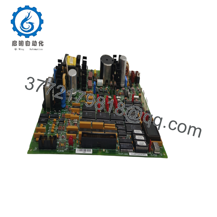
| Board Type | TCEA Emergency Overspeed Board |
| Primary Function | Turbine overspeed protection and protective processing |
| System Architecture | Triple Modular Redundant (TMR) |
| Installation Location | Protective Core (<P1>) |
| Processor Roles | X, Y, or Z Protective Processor |
| Communication | IONet Daisy Chain |
| Supported Inputs | Magnetic pickup speed signals, UV flame detector signals, synchronization signals |
| Trip Interface | Connected to TCTG Turbine Trip Board |
| Power Supply | Dedicated onboard power distribution |
| Application | Gas and Steam Turbine Control Systems |
4. Product Introduction
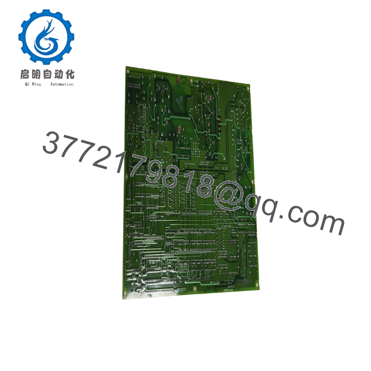
The GE DS200TCEAG1BNE is the TCEA Emergency Overspeed Board used in the GE Mark V turbine control platform. Installed in the Protective Core, it independently monitors turbine speed, processes overspeed protection logic, supervises flame detection inputs, and generates emergency trip commands without relying on the main control processor.
In a standard Mark V TMR system, three TCEA boards operate as the X, Y, and Z protective processors. Their outputs participate in a two-out-of-three voting scheme to determine whether a turbine trip should occur, providing fault tolerance for critical protection functions. Before replacement, verify the complete part number, hardware revision, and processor assignment.

- DS200TCEAG1BNE
- DS200TCEAG1BNE
5. Installation & Configuration Guide
Stage 1 – Pre-Installation Preparation (10 minutes)
⚠️ Safety First
- Notify operations and obtain shutdown approval.
- Shut down the turbine according to plant procedures.
- Lock out and tag out all control and auxiliary power sources.
- Wait at least 5 minutes for stored energy to discharge.
- Verify absence of voltage before opening the cabinet.
Tools Required
- ESD wrist strap
- PH1 screwdriver
- Digital multimeter (Fluke 115 or equivalent)
- Cable identification tags
- Smartphone for documentation
Data Backup
- Save Mark V configuration files.
- Record processor assignment (X, Y, or Z).
- Photograph all connectors.
- Record hardware revision and jumper positions.
Stage 2 – Removing the Existing Board (5–10 minutes)
- Open the protective core cabinet.
- Label every cable before disconnecting it.
- Disconnect IONet and interface connectors carefully.
- Remove retaining screws.
- Pull the board straight out to avoid connector damage.
- Inspect the backplane for bent pins, contamination, or oxidation.
⚠️ Keep the removed board available until the replacement has passed all functional tests.
Stage 3 – Installing the New Board (10 minutes)
- Wear an ESD wrist strap throughout installation.
- Verify the complete model number DS200TCEAG1BNE.
- Confirm the replacement is assigned to the correct X, Y, or Z processor position.
- Duplicate all jumper and hardware configuration settings.
- Insert the board completely into the rack.
- Reconnect all communication and interface cables.
Self-Checklist
- ✔ Model verified
- ✔ Correct processor position
- ✔ Jumpers duplicated
- ✔ Connectors secured
- ✔ Faceplate tightened
Stage 4 – Power-On & Functional Testing (15–20 minutes)
Pre-Power Inspection
- Verify control power supply.
- Inspect connector seating.
- Confirm grounding integrity.
Startup Procedure
- Energize the Mark V control cabinet.
- Observe diagnostic LEDs.
- Verify IONet communication.
- Confirm processor recognition by the control system.
- Test magnetic pickup input signals.
- Verify emergency trip logic during maintenance testing.
- Confirm synchronization and flame detection status where applicable.
⚠️ Troubleshooting
- IONet communication failure: Check JX1/JX2 communication chain.
- Processor not detected: Verify board position and hardware revision.
- Trip logic faults: Confirm processor assignment and voting configuration.
- Speed input errors: Inspect magnetic pickup wiring and termination boards.
6. Frequently Asked Questions (FAQ)
Q1. Can the DS200TCEAG1BNE be hot-swapped?
No. This board performs turbine protection functions. Removing it with power applied can disable critical protection and damage the control system. Always isolate power before replacement.
Q2. What is the primary function of this board?
The TCEA board independently monitors turbine speed, processes overspeed protection, supervises flame detection, supports automatic synchronization, and sends trip commands to the Turbine Trip Board when required.
Q3. Why are three TCEA boards installed in one Mark V system?
A standard Mark V turbine controller uses three TCEA boards operating as the X, Y, and Z protective processors. Their outputs are evaluated through two-out-of-three (2oo3) voting, allowing the system to tolerate a single processor fault while maintaining turbine protection.
Q4. Is the DS200TCEAG1BNE obsolete?
Yes. It is part of the legacy GE Mark V platform. New Original (New Surplus) inventory is limited, while professionally tested refurbished units remain widely used to support operating turbine fleets.
Q5. Will replacing this board erase my turbine control logic?
No. The application software is stored elsewhere in the Mark V system. However, you should always back up the system configuration and document processor assignments before replacing any protection board.
Q6. Why is processor assignment (X, Y, or Z) important?
Each TCEA board performs a dedicated role within the Triple Modular Redundant protection architecture. Installing a board in the wrong processor position or with incorrect hardware settings can prevent proper voting and may generate protection faults during startup.
Q7. What should be verified before returning the turbine to service?
A commissioning engineer should confirm:
- Correct board revision
- Correct X/Y/Z processor assignment
- Stable IONet communication
- Proper magnetic pickup input signals
- Functional emergency trip logic
- Healthy diagnostic LEDs
- Secure cabinet grounding
- Successful protective system self-tests
These checks eliminate most startup issues and help ensure the Mark V protection system performs as designed during turbine operation.



