
 WhatsApp: +86 16626708626
 Email:
  Phone: +86 16626708626
Description
3. Key Technical Specifications
| Parameter | Value |
|---|---|
| System Platform | GE Mark V Speedtronic |
| Function | Emergency overspeed protection & trip logic |
| Processor | Intel 80196 microprocessor |
| Memory | EPROM sockets (multiple configurable modules) |
| Protection Components | 3 onboard fuses (FU1–FU3) |
| Configuration | ~30 hardware jumpers |
| Connectors | Multiple signal & power connectors (J7, JK, JL, JW, JX1/JX2) |
| PCB Coating | Standard industrial coating |
| Functional Revision | B / T / F revision set |
| Installation Location | <P> core within Mark V rack |
| Weight | ~0.75–3 kg (vendor dependent listing) |
| Operating Role | Trip signal processing (overspeed + flame detection) |
4. Product Introduction
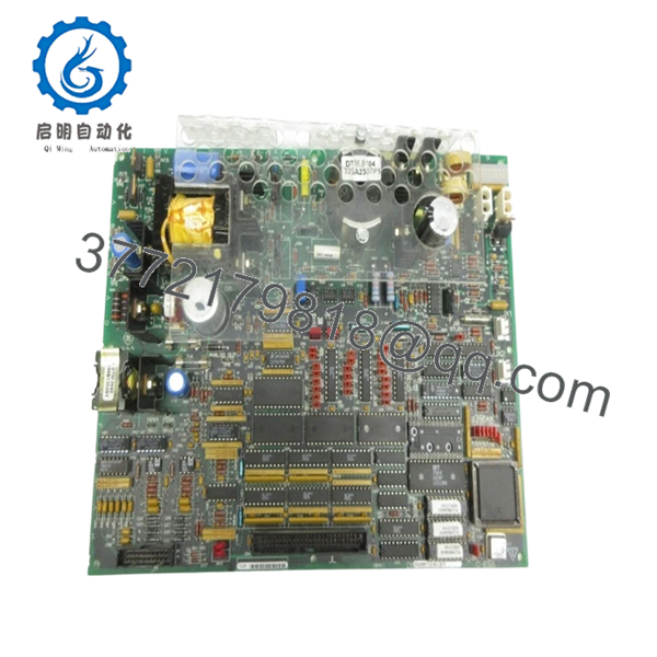
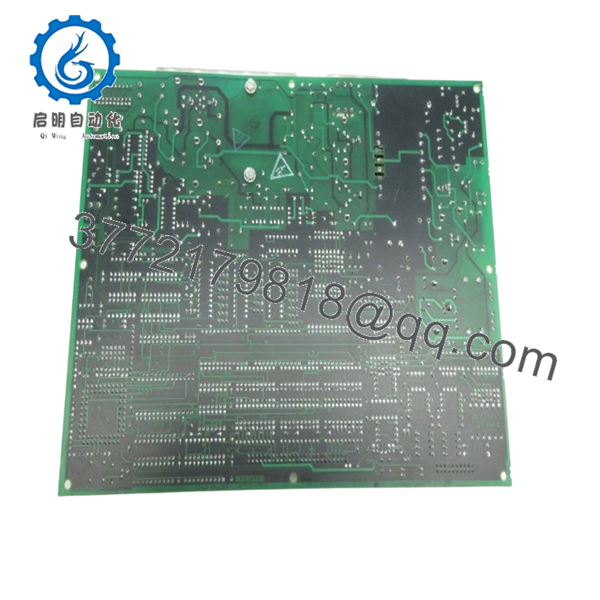
The GE DS200TCEAG1BTF is an emergency overspeed protection board used in the Mark V Speedtronic turbine control system. It processes turbine speed and flame detection signals and initiates shutdown logic when thresholds are exceeded.
In real turbine systems, this board is part of the critical protection layer. It operates independently of normal control loops to ensure immediate trip response under unsafe conditions, which is why it’s treated as a safety-relevant component during maintenance and replacement.
5. Installation & Configuration Guide
Stage 1: Pre-Installation Preparation (Estimated: 15 minutes)
- ⚠️ Safety First: Trip turbine to safe state, apply full lockout/tagout, verify zero energy.
- Tools Required: ESD strap, insulated screwdriver set, multimeter (Fluke 115 recommended), labeling tags, camera.
- Data Backup:
- Record turbine trip logs and system diagnostics
- Photograph jumper positions (critical)
- Document rack slot location (<P> core)
Stage 2: Removing the Old Module (Estimated: 10 minutes)
- Open Mark V panel and locate TCEA board.
- Label all connectors (J7, JK, JL, etc.).
- Disconnect cables carefully — no force.
- Release board retention hardware.
- Pull straight out to avoid backplane pin damage.
⚠️ Note: Keep the old board for jumper reference — do NOT discard yet.
Stage 3: Installing the New Module (Estimated: 15 minutes)
- ESD protection mandatory.
- Verify model: DS200TCEAG1BTF (revision compatibility matters).
- Configuration Clone (Critical):
- Replicate ALL jumper positions exactly
- Match fuse ratings (FU1–FU3)
- Insert board into rack — ensure full seating.
- Reconnect all connectors securely.
Self-Checklist:
- Jumpers identical
- Fuses verified
- Connectors seated
- Board fully inserted
Stage 4: Power-On & Testing (Estimated: 20–30 minutes)
Pre-Power Check:
- Verify no shorts on control power rails
Power-On Steps:
- Energize control system only (no turbine start).
- Check diagnostic LEDs/status.
- Verify communication with Mark V controller.
- Simulate overspeed condition (if test environment available).
- Confirm trip signal response.
⚠️ Troubleshooting Note:
- No trip response → jumper mismatch
- Fault alarms → firmware/EPROM mismatch
- Intermittent faults → connector seating issue
6. Frequently Asked Questions (FAQ)
Q1: Can this board be hot-swapped?
No. Absolutely not. This is part of a turbine protection system. Removing under power risks false trips or hardware damage. Always shut down the system fully.
Q2: Is this board obsolete?
Yes. The Mark V platform is legacy. Most units are sourced as surplus or refurbished. Lead times vary widely depending on availability.
Q3: What happens if I install the wrong revision (B/T/F mismatch)?
You may see inconsistent trip behavior or communication faults. In worst cases, protection logic won’t execute correctly. Always match revision levels when possible.
Q4: Will configuration carry over automatically?
No. This board relies heavily on hardware jumpers. If you don’t replicate them exactly, the system behavior will change.
Q5: Why are there so many jumpers on this board?
Because Mark V systems predate modern software-configurable designs. Hardware jumpers define logic paths, signal routing, and operational modes.
Q6: Can I upgrade to Mark VIe instead?
Not directly. That’s a full control system migration involving I/O, software, and HMI changes. This board is not cross-compatible.
Q7: What’s the most common failure mode?
- Fuse failure due to voltage spikes
- Aging EPROM modules
- Connector oxidation
I’ve replaced several where the issue was just a blown FU2 fuse — simple but easy to overlook.

- DS200TCEAG1BTF
- DS200TCEAG1BTF
SOP Quality Transparency (Inspection & Testing Process)
1. Inbound Inspection & Traceability
- Verified against GE OEM labeling and revision codes
- Serial number and PCB markings checked
- Visual inspection: no burnt traces, no capacitor bulging, no corrosion
2. Live Functional Testing
- Installed in a GE Mark V test rack
- Power-on diagnostics verified
- Signal simulation for overspeed trip
- Connector integrity checked
- Continuous runtime test: >24 hours
3. Electrical Parameter Testing
- Insulation resistance >10 MΩ @ 500 V
- Fuse continuity verified
- Ground path checked
4. Firmware & Configuration Verification
- EPROM presence and integrity verified
- Jumper configuration documented
- Revision (B/T/F) recorded
5. Final QC & Packaging
- QC sign-off with trace ID
- Anti-static ESD packaging
- Foam-protected heavy-duty carton
- QC Passed label applied
Test reports and live test videos available upon request.
Technical Pitfalls & Survival Guide
❗ 1. Jumper Misconfiguration (Most Critical)
This board depends heavily on jumper settings.
Avoidance: Take high-resolution photos before removal.
I’ve seen turbines refuse to start because one jumper was off by a single position.
❗ 2. EPROM Compatibility Issues
Different firmware sets can affect trip logic.
Avoidance: Keep original EPROMs if possible.
❗ 3. Fuse Replacement Errors
Using incorrect fuse ratings can damage the board.
Avoidance: Match exact specification (FU1–FU3).
Never “upgrade” fuse ratings — that’s asking for trouble.
❗ 4. Connector Misalignment
Multiple connectors look similar.
Avoidance: Label everything before removal.
One wrong connector = false trip or no protection.
❗ 5. ESD Damage
Older GE boards are not very forgiving.
Avoidance: Always use grounded wrist strap.
I’ve personally seen a replacement fail immediately due to static.


