
 WhatsApp: +86 16626708626
 Email:
  Phone: +86 16626708626
Description
3. Key Technical Specifications
| Parameter | Value |
|---|---|
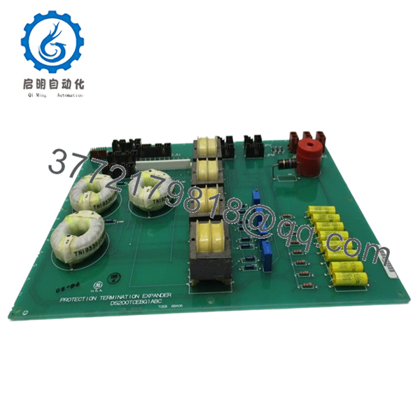
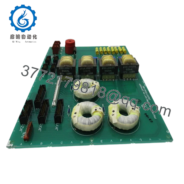
| Product Type | Protective Termination Expander Board (TCEB) |
| Series | GE Mark V Speedtronic |
| Functional Role | CT/PT signal scaling + protection signal routing |
| Installation Location | P1 core (interfaces with R5 TCCB board) |
| Signal Types | Current Transformer (CT), Potential Transformer (PT), flame detection |
| High Voltage Path | 335 V DC for flame detection circuits |
| Key Connectors | JMP, JU, JV, JVA, JWX, JPU, JPV |
| Communication | Passive signal routing (no CPU) |
| Configuration | No jumpers or software configuration |
| System Integration | Interfaces with TCCB, PTBA, TCEA boards |
| Application | Gas, steam, wind turbine control systems |
4. Product Introduction
The GE DS200TCEBG1ABC is a Protective Termination Expander Board used in the Mark V Speedtronic turbine control system. Its primary role is to scale CT/PT signals and route critical protection signals such as flame detection and overspeed inputs between boards.
In real turbine systems, this board sits in the P1 core and acts as a signal conditioning bridge between terminal boards (PTBA) and control boards (TCCB/TCEA). It does not execute logic but is critical for accurate voltage/current measurement and protection integrity. Engineers replace it when signal drift, isolation issues, or connector degradation appear.
5. Installation & Configuration Guide
Stage 1: Pre-Installation Preparation (Estimated Time: 15–20 min)
- ⚠️ Safety First:
- Shutdown turbine/control system
- Lock out/tag out all energy sources
- Wait minimum 10 minutes (high-voltage circuits present, including 335 V DC lines)
- Tools Required:
- ESD wrist strap
- PH1 screwdriver
- Multimeter (Fluke 115 recommended)
- Labels + smartphone
- Data Backup:
- Photograph all connectors (JMP, JV, JWX, etc.)
- Document cable routing between TCCB, PTBA, TCEA
- Record slot location (P1 core)
Stage 2: Removing the Old Module (Estimated Time: 10–15 min)
- Open Mark V cabinet and locate TCEB board in P1 core.
- Label each connector carefully (many similar multi-pin cables).
- Disconnect cables—do not twist or pry.
- Release mounting hardware.
- Pull board straight out from backplane.
- ⚠️ Note:
This board handles multiple critical protection signals—mislabeling connectors will cause serious system faults.
Stage 3: Installing the New Module (Estimated Time: 15 min)
- Apply ESD protection.
- Verify exact model: DS200TCEBG1ABC (revision matters)
- Insert board fully into P1 slot—ensure proper seating
- Reconnect all cables exactly as documented
- Self-Checklist:
- All connectors matched correctly
- Board fully seated
- No bent pins
- Cable routing unchanged
Stage 4: Power-On & Testing (Estimated Time: 20–30 min)
- Pre-Power Check:
- Verify no short circuits
- Check CT/PT wiring continuity
- Power-On Steps:
- Energize control cabinet only
- Monitor system diagnostics
- Verify voltage/current readings
- Check flame detection signals
- Return system to service gradually
- ⚠️ Troubleshooting Note:
- Incorrect voltage readings → CT/PT wiring mismatch
- Flame detection fault → JWX/JU connector issue
- No signals → board seating or connector error

- DS200TCEBG1ABC
- DS200TCEBG1ABC
6. Frequently Asked Questions (FAQ)
Q1: Does this board require configuration or programming?
No.
There are no jumpers or software settings. All functionality is hardware-based signal routing.
Q2: What makes this board critical if it has no CPU?
Because it handles protection signals.
If CT/PT scaling is wrong, your turbine sees incorrect voltage/current. That can trigger false trips—or worse, fail to trip when needed.
Q3: Can I replace DS200TCEBG1ABC with another revision?
❗ Not always.
Different revisions (A/B/C variants) are not fully backward-compatible in all assemblies. Verify before installation.
Q4: Can this board be hot-swapped?
No.
You are dealing with high-voltage signal paths (up to 335 V DC). Removing under power is unsafe and risks system damage.
Q5: What typically fails on this board?
From field experience:
- Connector wear and oxidation
- Signal drift in scaling circuits
- Insulation degradation in high-voltage paths
Q6: Why is availability limited and pricing high?
Mark V is obsolete, but still widely installed in power plants.
This board has no modern drop-in replacement, so supply is limited to surplus and refurbished stock.
Q7: What’s the biggest installation mistake?
❗ Connector mix-up.
I’ve seen engineers swap two similar connectors—system powered up with completely wrong voltage readings. That took hours to trace. Label everything before removal.


