
 WhatsApp: +86 16626708626
 Email:
  Phone: +86 16626708626
Description
3. Key Technical Specifications
| Parameter | Value |
|---|---|
| System Compatibility | GE Mark V Speedtronic |
| Function Type | Analog I/O interface board |
| Analog Input Range | −10 V to +10 V |
| Analog Output Range | −10 mA to +10 mA |
| Power Supply | 24 V DC, approx. 500 mA |
| Connectors | 4 × 34-pin, 2 × 40-pin |
| Jumpers | 6 configuration jumpers |
| Indicators | 6 LED status indicators |
| Operating Temperature | −40°C to +70°C |
| Dimensions | ~190 × 120 × 40 mm |
| Weight | ~0.5 kg |
4. Product Introduction
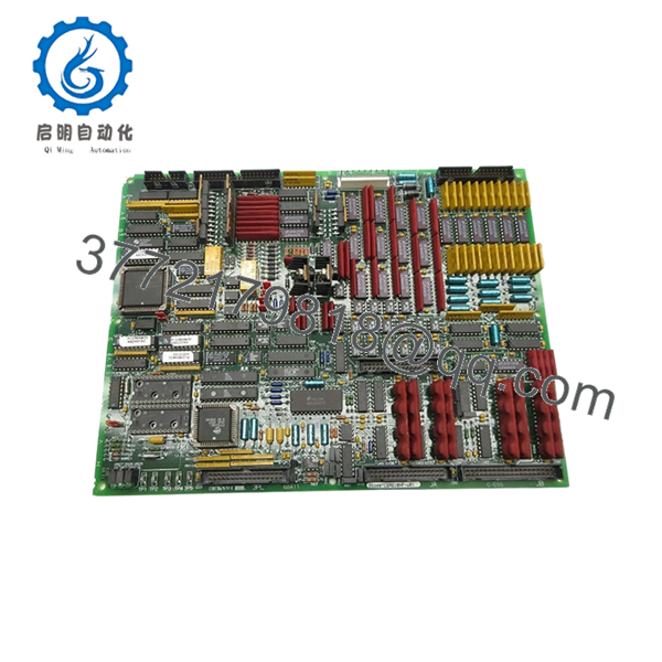
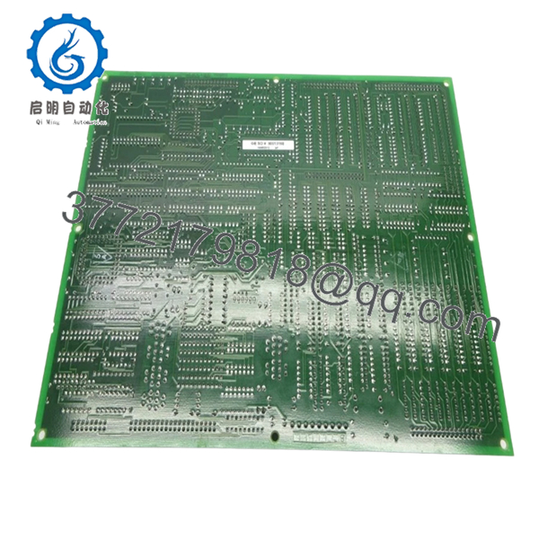
The GE DS200TCQAG1BHF-W01 is an analog I/O board used in the Mark V Speedtronic turbine control system, handling signal conditioning and conversion between field analog signals and the control processor. It acts as a bridge between analog instrumentation and digital control logic.
In real plant systems, this board sits right in the signal path—any drift, noise, or failure here directly impacts turbine control stability. Engineers stick with the exact part number because even small differences in analog front-end circuitry can affect scaling, filtering, and loop response.
5. Installation & Configuration Guide
Stage 1: Pre-Installation Preparation (Estimated Time: 10–15 min)
- ⚠️ Safety First:
Shutdown turbine or drive system, apply lockout/tagout, wait at least 5 minutes. - Tools Required:
ESD strap, PH1 screwdriver, Fluke 115 multimeter, labeling tape, smartphone. - Data Backup:
- Photograph all connectors and cable routing
- Record analog signal ranges (critical for calibration)
- Note any abnormal readings before shutdown
Stage 2: Removing the Old Module (Estimated Time: 5–10 min)
- Open Mark V cabinet and locate the board.
- Label all connectors (J1–J6 typical).
- Disconnect cables carefully—no pulling on harnesses.
- Release retaining clips.
- Pull board straight out to avoid backplane damage.
- Inspect connectors for oxidation or looseness.
- ⚠️ Note: Keep the old board nearby for jumper reference and troubleshooting.
Stage 3: Installing the New Module (Estimated Time: 5–10 min)
- Wear ESD protection.
- Verify model: DS200TCQAG1BHF-W01 (suffix must match exactly).
- Configuration Clone (Critical):
- Replicate all 6 jumper settings
- Match any field modifications or resistor packs
- Insert board into correct slot.
- Ensure full seating (no partial engagement).
- Reconnect wiring exactly as labeled.
- Self-Checklist:
[ ] Jumper settings matched
[ ] Wiring correct
[ ] Fully seated
[ ] No bent pins
Stage 4: Power-On & Testing (Estimated Time: 10–15 min)
- Pre-Power Check:
Verify no shorts on 24 V rail using multimeter. - Power-On Steps:
- Power control rack only.
- Observe LED indicators (status confirmation).
- Verify analog signals via HMI or diagnostics.
- Check scaling accuracy (compare with field instruments).
- Perform dry-run test before enabling turbine.
- ⚠️ Troubleshooting Note:
- Signal drift → check grounding and shielding
- No input → verify connector seating
- Output mismatch → suspect jumper misconfiguration

- DS200TCQAG1BHF-W01
- DS200TCQAG1BHF-W01
6. Frequently Asked Questions (FAQ)
Q1: Can this board be hot-swapped?
No. Mark V systems are not designed for hot-swapping. Removing it under power can damage the rack or corrupt signals.
Q2: Is DS200TCQAG1BHF-W01 obsolete?
Yes. Mark V is a legacy platform. Availability depends on surplus stock, and lead times can vary from immediate shipment to several weeks.
Q3: What does this board actually do in the system?
It converts analog signals to digital (A/D) and digital back to analog (D/A), acting as the interface between sensors/actuators and the control processor.
Q4: Are different DS200TCQA variants interchangeable?
Not reliably. GE used multiple revisions (G1BHF, G1BFD, etc.). I’ve seen loop instability caused by slight differences in analog filtering.
Q5: Will I need to recalibrate after replacement?
Yes, in many cases. Even with identical hardware, analog tolerances can shift slightly. Always verify scaling and loop response.
Q6: Why is jumper configuration so critical?
Because jumpers define signal routing, scaling, or termination. One incorrect jumper can offset readings or disable a channel entirely.
Q7: What’s the most common failure mode?
- Analog component drift (op-amps, references)
- Capacitor aging
- Noise issues from degraded grounding
Technical Pitfall & Survival Guide
1. Firmware/System Expectation Mismatch
Even though this is an I/O board, the Mark V controller expects specific signal behavior.
→ Always verify system configuration before replacement.
2. Jumper Misconfiguration
❗ Most frequent issue
I’ve seen a single jumper error shift a 4–20 mA signal into nonsense values.
→ Take photos before removal. Always.
3. Wiring Errors
Connectors look identical.
→ Label everything. Don’t trust memory under outage pressure.
4. Power Load Oversight
This board draws ~500 mA at 24 V.
→ Check total rack load—especially in older cabinets with marginal supplies.
5. ESD Damage
❗ Real-world failure
One winter install without grounding → board failed immediately on power-up.
→ Always use ESD protection.


