
 WhatsApp: +86 16626708626
 Email:
  Phone: +86 16626708626
Description
Key Technical Specifications
| Parameter | Specification |
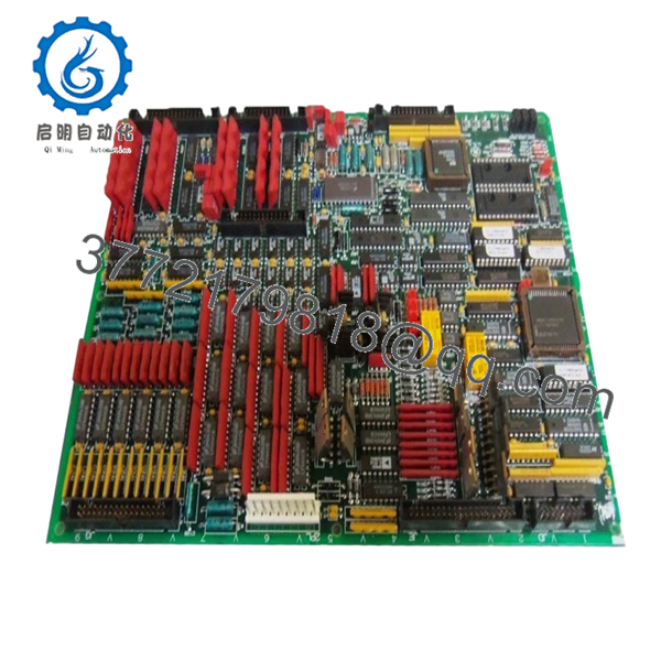
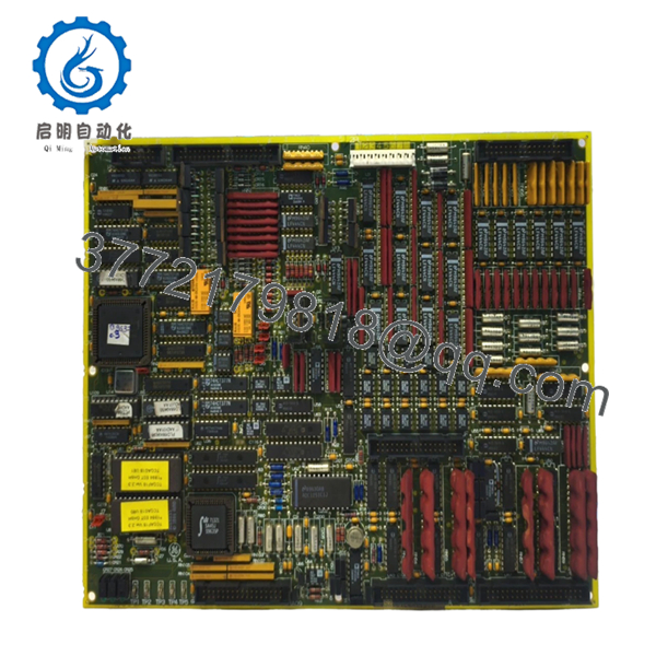
| Board Identifier | TCQC (Analog Configuration Board) |
| System Compatibility | GE Speedtronic Mark V (TMR or Simplex) |
| Input Signals | LVDT/LVIT, Thermocouples, 4-20 mA, 1-5 VDC |
| Output Signals | Servo Coil Drivers, 4-20 mA Outputs |
| Revision Level | G1BJG (High-level revision) |
| Microprocessor | Onboard Intel-based signal processor |
| Isolation | Galvanic isolation between I/O and Backplane |
| Operating Temp | 0 to 60°C (32 to 140°F) |
| Mounting | Standard Mark V Card Rack (R1, S1, or T1 cores) |
Product Introduction
The GE DS200TCQCG1BJG is a cornerstone Analog Configuration Board (TCQC) within the Speedtronic Mark V turbine control system. This board is the primary gateway for critical analog signals, including thermocouple inputs for exhaust temperature monitoring and LVDT/LVIT feedback for fuel valve positioning. In a Triple Modular Redundant (TMR) setup, the TCQC board resides in the R1, S1, and T1 cores to ensure voting logic is applied to all vital turbine feedback.
The G1BJG revision represents a sophisticated build that integrates high-speed signal processing to minimize scan times and improve governor response. Because this card handles both sensitive low-level inputs and high-current servo outputs, it is a frequent focal point for maintenance. This “New Surplus” unit ensures the onboard capacitors and integrated circuits have not been degraded by the high-heat cycles typical of a 24/7 power generation environment.
Installation & Configuration Guide
Stage 1: Pre-Installation Preparation (Estimated Time: 20 mins)
- ⚠️ Safety First: Replacing a TCQC board involves valve feedback and temperature loops. Never replace this board with the turbine online. Notify the control room and ensure the unit is in a “Safe” state.
- Tools Required: ESD wrist strap, Phillips #1 screwdriver, and a calibrated signal generator (for post-install loop checks).
- Firmware Note: The TCQC board uses socketed EPROMs. Check if your new DS200TCQCG1BJG includes these or if you must migrate the site-specific chips (e.g., U6 and U7) from the old board.
Stage 2: Removing the Old Module
- De-energize the Mark V control cabinet power.
- Photograph all ribbon cables and hardware jumpers (JP1, JP2, etc.). The TCQC is heavily dependent on hardware jumper settings for signal scaling.
- Carefully disconnect the ribbon cables from the front of the board. These cables are fragile; pull by the tabs, not the wires.
- Unscrew the retention fasteners and pull the card straight out to avoid bending the backplane pins.
Stage 3: Installing the New Module (Estimated Time: 30 mins)
- Jumper Configuration (Critical): Place the old and new boards side-by-side. Move every jumper on the new board to match the old one exactly. This sets your analog input types (e.g., mA vs. Voltage).
- IC Migration: If required, carefully swap the socketed EPROMs. Use an IC puller and ensure the “notch” points the same direction as on the old board.
- Slide the card into the rack. Firmly seat the card into the backplane.
- Reconnect the ribbon cables and secure the retention screws.
- Self-Checklist: [ ] Jumpers match, [ ] EPROMs oriented, [ ] Cables locked in place.
Stage 4: Power-On & Testing
- Restore power to the cabinet.
- Access the Mark V Operator Interface (HMI) and check for “I/O Configuration Mismatch” or “Voter Alarms.”
- Loop Check: Verify thermocouple and LVDT readings. If a valve feedback is showing -25% or 125%, re-verify the JP jumpers on the TCQC board.
- Perform a calibration for any servo outputs driven by this card using the “AutoCal” utility if necessary.

- DS200TCQCG1BJG
Frequently Asked Questions (FAQ)
Q: Can I replace a DS200TCQCG1B with this G1BJG version?
A: Yes. The “JG” at the end typically denotes a specific revision or manufacturing factory code, but it is functionally compatible with the G1B series. Ensure your jumpers are matched, as that dictates the board’s behavior more than the revision suffix.
Q: My “LVDT Signal Loss” alarm is still active after swapping the board. Why?
A: If the board is new, check the excitation voltage jumpers. The TCQC provides the excitation for the LVDT sensors. If the jumpers are in the wrong position, the sensors won’t get power. If jumpers are correct, check the ribbon cable connecting the TCQC to the TBCB (Terminal Board).
Q: Why do I have to move the chips (EPROMs) from my old board?
A: The software logic on those chips is often specific to your turbine’s control constants. While the board is the “muscle,” the EPROMs are the “instructions.” Using the wrong chips can lead to “Configuration Fatal Errors” or incorrect scaling of critical measurements like turbine speed or exhaust temp.
Q: Is it safe to leave the cabinet power on if I only pull the TCQC board?
A: No. The Mark V backplane is a shared bus. Pulling a card like the TCQC while powered can cause a “Bus Hang” or a logic spike that could potentially crash the other control cores (R, S, or T) and trip the unit if it’s currently running.
Q: What is the most common failure mode for this board?
A: Usually, it’s the analog-to-digital converters (ADCs) or the electrolytic capacitors. If you see erratic “jitter” in your HMI temperature readings that wasn’t there before, it’s a classic sign that the filtering capacitors on the TCQC are failing.


