
 WhatsApp: +86 16626708626
 Email:
  Phone: +86 16626708626
Description
3. Key Technical Specifications
| Parameter | Value |
|---|---|
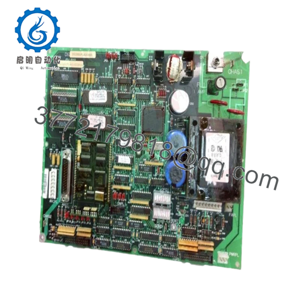
| Model Number | DS200UPLAG1B |
| Manufacturer | GE General Electric |
| Series | Speedtronic Mark V |
| Functional Acronym | UPLA |
| Product Type | LAN Power Supply Circuit Board |
| Primary Application | Turbine Control System Power Distribution |
| Compatible Systems | GE Mark V Turbine Control Platforms |
| Input Power Environment | 24 V DC control cabinet supply |
| Connectors | Two 26-pin connectors, one 8-pin connector |
| Protection Features | Onboard fuse protection |
| User Controls | Toggle switch, reset pushbutton |
| Jumper Configuration | 17 configurable jumpers |
| DIP Switches | 16-position switch configuration |
| PCB Coating | Normal conformal coating |
| Mounting Method | Rack-mounted PCB |
| Operating Temperature | 0 °C to +60 °C typical cabinet environment |
| Storage Temperature | −40 °C to +85 °C |
| Approximate Dimensions | 8.5 in × 11 in PCB format |
| Product Status | Legacy / Obsolete GE Hardware |
4. Product Introduction
The GE DS200UPLAG1B is a LAN Power Supply Circuit Board designed for GE Speedtronic Mark V turbine control systems used in gas, steam, and industrial turbine applications. It provides regulated power distribution and communication support for interconnected Mark V control hardware.
In field service environments, the DS200UPLAG1B is commonly replaced during aging Mark V lifecycle maintenance projects where intermittent communication faults, unstable LAN voltage conditions, or failed onboard fuse protection begin causing nuisance trips or startup delays. Engineers generally prefer maintaining the original Mark V architecture instead of forcing an immediate migration to Mark VIe during outage windows.
- DS200UPLAG1B
5. Installation & Configuration Guide
Stage 1: Pre-Installation Preparation (Estimated Time: 10 Minutes)
⚠️ Safety First
- Notify plant operations and schedule control downtime.
- Verify the turbine and auxiliary systems are in a safe shutdown condition.
- Apply full lockout/tagout procedures to cabinet power feeds.
- Wait at least 5 minutes for internal capacitors to discharge.
Tools Required
- ESD wrist strap
- PH1 screwdriver
- Fluke 115 multimeter
- Wire markers and labels
- Smartphone for reference photos
- Flashlight for cabinet inspection
Data Backup
- Backup current Mark V configuration files.
- Record cabinet slot location and node settings.
- Photograph all DIP switch and jumper positions.
- Document ribbon cable orientation carefully.
❗This matters more than people think. I have seen experienced techs reverse a ribbon cable after a midnight outage and lose half a day chasing phantom LAN faults.
Stage 2: Removing the Old Module (Estimated Time: 5–10 Minutes)
- Open the Mark V cabinet access panel.
- Label all field and ribbon cable connections.
- Disconnect connectors carefully. Never yank ribbon cables by the wires.
- Remove retaining screws from the PCB corners.
- Pull the board straight out from the rack guides.
- Inspect:
- Backplane connector pins
- Dust buildup
- Burn marks near fuse areas
- Loose metallic debris
⚠️ Note
Do not discard the old board immediately. Keep it beside the cabinet until the replacement is fully commissioned and stable under load.
Stage 3: Installing the New Module (Estimated Time: 10 Minutes)
- Wear a grounded ESD strap before handling the PCB.
- Verify the exact model: DS200UPLAG1B.
- Inspect the replacement board for:
- Cracked solder joints
- Damaged connectors
- Fuse integrity
- Shipping damage
Configuration Clone (Crucial)
- Replicate all jumper and DIP switch settings exactly from the original board.
- Confirm toggle switch positions match the removed unit.
- Verify ribbon cable orientation before insertion.
❗This is the most common installation mistake on Mark V boards. A single incorrect switch setting can break LAN communication across the rack.
I once saw a contractor replace a UPLA board during a turnaround and leave one termination switch in the factory default position. The system threw intermittent communication alarms for 18 hours before anyone caught it.
- Slide the board evenly into the rack rails.
- Tighten mounting screws evenly.
- Reconnect all wiring and ribbon cables carefully.
Self-Checklist
- DIP switches match
- Jumpers verified
- Ribbon cables aligned correctly
- Fuse inspected
- Board fully seated
- Retention screws secured
Stage 4: Power-On & Testing (Estimated Time: 10–15 Minutes)
Pre-Power Check
- Verify no shorts exist on the 24 V DC rail using a multimeter.
- Check cabinet grounding continuity.
- Confirm fuse integrity before energizing.
Power-On Steps
- Energize the Mark V rack only.
- Observe startup behavior carefully.
- Check for:
- Proper LED status
- No overheating smell
- Stable communication indicators
- Connect engineering workstation software.
- Verify:
- Rack communication
- Board recognition
- Stable LAN status
- No watchdog or communication alarms
- Perform dry-run signal verification before enabling field devices.
⚠️ Troubleshooting Note
- Continuous fault indications usually point to:
- Incorrect DIP switch settings
- Ribbon cable reversal
- Firmware incompatibility
- Improper rack seating
- If communication drops intermittently:
- Check onboard fuse condition
- Inspect grounding and shield termination
- Verify power supply stability under load
I have seen old Mark V cabinets where oxidized backplane connectors caused intermittent faults that looked exactly like bad boards. Clean the rack before blaming the replacement module.
6. Frequently Asked Questions (FAQ)
Q1: Can the DS200UPLAG1B be hot-swapped?
No. Do not hot-swap this board in a live Mark V system.
Removing or inserting the board under power can corrupt LAN communication and potentially damage the backplane. Shut down cabinet power first.
Q2: Is the DS200UPLAG1B obsolete?
Yes. The GE Mark V platform is legacy hardware and OEM production has been discontinued. Most available inventory today comes from surplus industrial stock or specialized turbine control suppliers.
Plants still running Mark V systems typically maintain strategic spare inventory because turbine downtime costs usually outweigh immediate migration expenses.
Q3: What does the “B” suffix mean in DS200UPLAG1B?
The suffix indicates a functional hardware revision. Revision changes can affect compatibility, jumper layouts, or firmware interaction.
❗Do not assume all UPLA revisions are interchangeable. Always verify the full part number and suffix before ordering.
Q4: Will replacing this board erase my turbine logic?
Normally no. The DS200UPLAG1B functions primarily as a LAN power supply and communication support board, not the primary logic storage processor.
Still, always back up:
- Control constants
- Configuration files
- Network settings
- Operator displays
Never trust a 20-year-old hard drive during a turbine outage.
Q5: Why are DIP switches and jumpers so important on this board?
Because factory defaults almost never match site configuration.
This board contains multiple configurable jumpers and switch banks that affect communication and operational behavior. A mismatch can trigger:
- Communication timeouts
- Rack faults
- Startup failures
- Intermittent LAN instability
Take photos before removal. Every experienced controls engineer learns this lesson eventually.
Q6: What testing is performed before shipment?
A proper QC workflow should include:
- OEM part verification
- Anti-counterfeit inspection
- Visual PCB inspection under magnification
- Fuse and continuity testing
- Power-on testing in a genuine Mark V rack
- Communication handshake verification
- 24-hour thermal stability testing
- Insulation resistance testing using a 500 V Megger
- ESD-safe packaging and final QC signoff
We strongly recommend requesting actual test reports and startup videos before shipment approval.
Q7: What is the most common installation failure with this board?
Ribbon cable orientation and switch mismatch.
Honestly, this design is a bit unforgiving compared to newer DCS hardware. One reversed cable or incorrect switch position can create faults that look like a failed processor or network issue.
Take detailed photos before touching anything. That single habit prevents most avoidable rework.
Keep these checks in mind and you’ll save yourself 90% of typical rework time.


