
 WhatsApp: +86 16626708626
 Email:
  Phone: +86 16626708626
Description
3. Key Technical Specifications
| Parameter | Specification |
| Manufacturer | General Electric (GE) |
| Part Number | DS200VPBLG1A |
| Series Compatibility | Speedtronic Mark V, LS2100 Static Starter, and LCI Systems |
| Functional Acronym | VPBL |
| Board Structure | Multilayer PCB with dedicated, isolated digital and analog power planes |
| Slot Configuration | Integrates with J2 and J3 rack backplane interfaces |
| Card Support (Slot J2) | Supports 1x DSPC board, I/O extenders, and up to 3x FCGD boards |
| Test Points | 60x high-access, spring-loop diagnostic test points |
| Wiring Interfaces | 10x high-current power bugs | 1x 34-pin exciter ribbon connector |
| Diagnostics Connector | 26-pin discrete cable connector for direct J1 processor I/O |
| Tachometer Interface | Configure via onboard jumpers and a 12-pin terminal block |
| Operating Temperature | 0 to +65 °C |
4. Product Introduction & Supply Chain Strategy
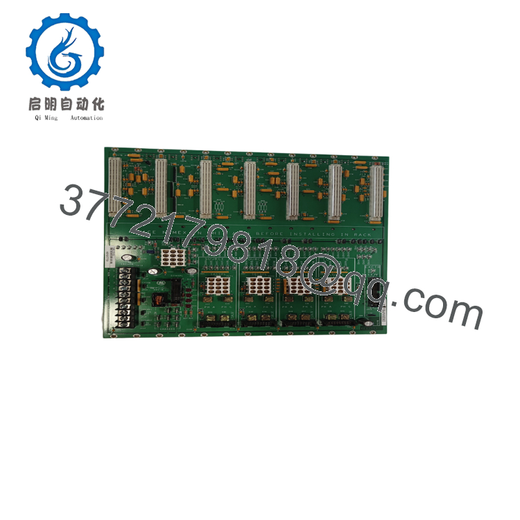
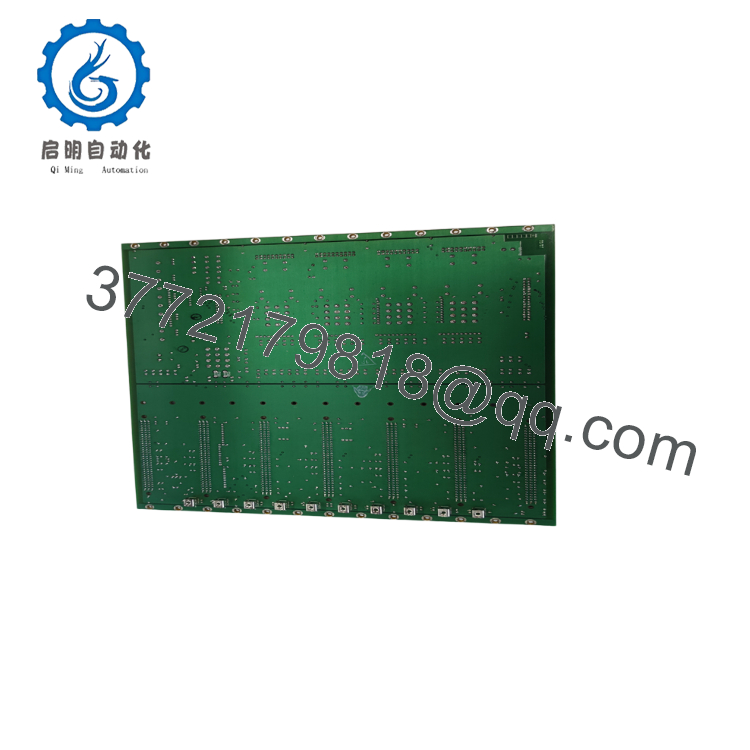
The GE DS200VPBLG1A is a VME Backplane Board (VPBL) engineered for Load Commutator Inverter (LCI) control enclosures, LS2100 static starters, and Speedtronic Mark V gas turbine control platforms. Serving as the primary communications spine, this multilayer card provides clean power distribution and interconnect routing across critical system boards, including Digital Signal Processor Cards (DSPC) and Gate Distribution Boards (FCGD). The board’s physical layout is divided into J2 and J3 functional zones, strategically isolating noise-sensitive analog traces from high-frequency digital signaling lines to protect signal integrity.
Because the backplane connects every processor, gate driver, and feedback card in the rack, it is a catastrophic single point of failure. Buying a refurbished backplane is a high-risk gamble; micro-fractures in solder joints, degraded bypass capacitors, or carbon tracking from dust are impossible to detect visually but will cause intermittent system lockups. Opting for a New Surplus DS200VPBLG1A provides a zero-hour OEM-grade solution, significantly reducing your Total Cost of Ownership (TCO) and guaranteeing the signal stability required for multi-year turbine operating campaigns.
5. Installation & Configuration Guide
Stage 1: Pre-Installation (Prep & Safety)
- Energy Isolation: Completely de-energize the entire rack frame. Turn off and lock out the main AC and DC control feeds. Verify that all 10 power bugs read 0 V using a digital multimeter.
- Labeling & Capture: Photograph the entire assembly. Carefully label every power wire, the 34-pin ribbon connector, and the 26-pin diagnostics connector.
- ESD Protocol: Put on a grounded ESD wrist strap before handling the replacement backplane to safeguard static-sensitive bus traces.
Stage 2: Removal
- Disconnect Cables: Unplug all ribbon cables and remove the wiring from the 12-pin tachometer terminal block. Unscrew the heavy-gauge wires attached to the 10 power bugs.
- Module Disassembly: Carefully remove all card modules (DSPC, FCGD) seated into the backplane connectors.
- Board Extraction: Back out all frame mounting screws systematically. Keep the backplane perfectly flat and level while pulling it away from the chassis guides to prevent warping the substrate or scratching the traces.
Stage 3: Installation (Clone & Seat)
- Jumper & Terminal Cloning: Replicate all jumper settings and verify tachometer terminal blocks on the new board to exactly match the old card’s configuration.
- Chassis Alignment: Carefully slide the new DS200VPBLG1A into the chassis. Hand-tighten all mounting screws across the board surface before tightening them to standard torque specifications.
- Wiring & Connection: Reconnect the heavy-gauge power lines to the 10 power bugs, making sure they are securely torqued. Reattach the 34-pin and 26-pin connectors, ensuring they are fully latched. Re-insert all VME processing and I/O cards.
Stage 4: Power-On & Testing
- Cold Check: Run a point-to-point resistance check on the primary power buses to confirm there are no physical shorts to the chassis ground.
- Power-Up: Apply control power and observe the processor boot sequence.
- Diagnostic Verification: Utilize the 60 spring-loop test points with an oscilloscope or high-impedance multimeter to verify that both the isolated digital and analog power planes are operating within factory limits.

- DS200VPBLG1A
- DS200VPBLG1A
6. Firmware/Software Versions & Upgrade Notes
The DS200VPBLG1A does not contain programmable flash memory or microcontrollers, meaning it does not carry internal firmware. However, because it routes essential timing and diagnostic signals directly to the primary J1 processor, physical revision compatibility is highly critical.
The G1A designator specifies the standard factory revision. If you are replacing an older revision board (e.g., legacy revisions without conformal coating), verify that the routing pins for your tachometer pulse streams match your existing sensors. Note that jumping functional revisions can occasionally modify default jumper placements for tachometer power supplies (such as E0V2 or E1V1). Always cross-reference your site schematics to ensure the new jumper positions correspond to your specific field instrument wiring.
7. Frequently Asked Questions (FAQ)
- Why is the backplane split into separate analog and digital power planes? This separate layout prevents high-frequency electrical noise from the digital logic chips (such as clock pulses and bus switching) from bleeding into sensitive analog measurement circuits (like tachometers and current transformers). Keeping these planes isolated prevents signal corruption and system trip faults.
- Is this a refurbished or repaired board? No. This DS200VPBLG1A is a genuine New Surplus unit. It has never been used in an active control panel and is free from repair solder work, connector pin wear, or component aging. It is stored in a clean, climate-controlled warehouse to ensure absolute structural and electrical integrity.
- What are the 60 spring-loop test points used for? These built-in test loops provide engineers with safe, direct physical access to measure critical analog and digital signals. They are extremely useful for troubleshooting actuator current phases, DC rail outputs, and tachometer feedback signals without having to back-probe connectors or risk shorting out adjacent components during diagnostic testing.
- Can I replace this backplane while the system is running? Absolutely not. The backplane serves as the central communication and power routing bus for the entire system chassis. Removing it during operation will immediately shut down all processors and gate drivers, resulting in a sudden, unmanaged system crash that can cause severe damage to your turbine or drive train.
- What do the 10 power bugs on this board connect to? These power bugs are heavy-duty, threaded brass terminals used to bring robust, high-current power feeds (such as the main 24 Vdc or 125 Vdc supply rails) directly onto the backplane. This provides stable power distribution across all connected control, processing, and I/O expansion boards within the rack.



