
 WhatsApp: +86 16626708626
 Email:
  Phone: +86 16626708626
Description
3. Key Technical Specifications
| Parameter | Specification Value |
| Functional Acronym | VPBL (VME Power Backplane Board) |
| Group Designation | G1 (Group 1 application specific layout) |
| Revision Level | 1AF (Includes factory component enhancements) |
| Input Voltage Rails | Supports multi-rail DC distribution (+5 V DC, \pm15 V DC, +24 V DC) |
| Circuit Protection | Integrated fuse holders and transient surge suppression paths |
| Bus Compatibility | Proprietary Mark V control rack framework |
| Connectors | High-current multi-pin headers, ribbon connectors, and screw terminals |
| Isolation Barrier | Heavy-duty board substrate designed for high dielectric isolation |
| Test Points | Onboard voltage test pins for direct multimeter diagnostic access |
| Mounting Orientation | Vertical or rear rack-frame mounting configurations |
| Environmental Limits | Operates at up to 60°C inside sealed industrial cabinets |
4. Product Introduction & Supply Chain Strategy
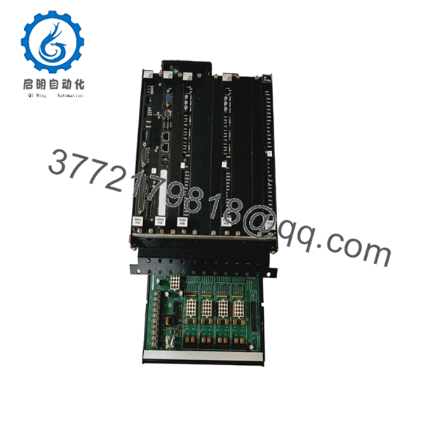
The GE DS200VPBLG1AF is a fundamental power distribution and routing hub engineered for the legacy Speedtronic Mark V turbine control system. Operating as the primary Power Backplane (VPBL) board, this Group 1 card serves as the central backbone that receives raw operating power, filters electrical noise, and distributes stabilized multi-rail DC power to adjacent control and processor boards within the drive rack. Featuring the rugged 1AF hardware revision, it integrates robust circuit protection, heavy-duty bus traces, and diagnostic test points to ensure stable voltage delivery to critical turbine protection circuits.
From an inventory and procurement standpoint, sourcing this module as a New Surplus asset is highly strategic. Because the VPBL board manages power distribution for an entire hardware subset, its failure instantly shuts down all dependent modules, creating an immediate, full-scale plant outage. Opting for a verified New Surplus card completely bypasses the degradation hazards of refurbished or used components—such as heat-stressed traces or weakened dielectric insulation. This strategy optimizes Total Cost of Ownership (TCO), secures maximum asset life, and avoids the staggering costs of unscheduled downtime.

- DS200VPBLG1AF
5. Installation & Configuration Guide
Stage 1: Pre-Installation (Prep & Safety)
- Perform a total power shutdown of the entire turbine control cabinet. Open and lock out the primary AC/DC incoming feeders and the main battery backup lines supplying the panel.
- Verify that you are wearing a fully functional, grounded ESD wrist strap connected to a designated grounding bus.
- Use a camera to thoroughly document all cable connections, individual wire labels, and the status of onboard replaceable fuses.
Stage 2: Removal
- Carefully unplug all power supply harnesses, multi-conductor ribbon cables, and auxiliary ground wires from the face of the board.
- Support the board frame while removing the mounting screws that secure the VPBL backplane to the rack chassis standoffs.
- Extract the card smoothly from the chassis, taking extreme care not to scrape or force the rear solder points against adjacent sheet metal brackets.
Stage 3: Installation (Clone & Seat)
- Check that all fuse ratings, hardware links, and physical configuration settings on the new DS200VPBLG1AF precisely match the original pulled board.
- Position the replacement card over the chassis mounting standoffs, making sure it aligns flush without binding.
- Secure the mounting screws in a balanced, crossways sequence to prevent flexing the board substrate.
- Reconnect all power harnesses and ribbon cables to their exact factory headers, ensuring they snap securely into place.
Stage 4: Power-On & Testing
- Re-energize the primary power breakers supplying the control panel.
- Before booting the rest of the rack, utilize a digital multimeter at the onboard diagnostic test points to verify that the +5 V, +15 V, -15 V, and +24 V DC voltage levels are completely stable and within specification.
- Observe adjacent rack modules to confirm they initialize smoothly and verify through the HMI configuration panel that no system power faults or bus voltage alarms are active.
6. Firmware/Software Versions & Upgrade Notes
- Hardware-Driven Baseline: As a dedicated power routing and backplane board, the DS200VPBLG1AF operates on pure hardware principles and does not possess programmable microprocessor firmware or software logic registers.
- Revision Matching: The 1AF designation denotes a fully backward-compatible revision layer. It can confidently replace older Group 1 variants (such as 1A or 1AE) without requiring soft-logic rewrites or system configuration modifications inside your application code.
- Live Adjustments Danger: Never install, pull, or adjust any cables, fuses, or jumpers on this backplane while the power supply is turned on. Because this module carries high-current distribution rails, making modifications while energized will cause severe electrical arcing, which will destroy this card and permanently damage any connected microprocessor boards across the system.
7. Frequently Asked Questions (FAQ)
What defines a “New Surplus” VPBL board over a refurbished alternative?
Our New Surplus cards are original, unused GE components that have never been deployed in an active production environment. They are typically sourced from cancelled industrial projects, system upgrade overstocks, or long-term warehouse spares. Because they have never seen thermal or electrical loads, they are entirely free from the trace degradation and micro-fractures that commonly affect used or refurbished parts pulled from decommissioned facilities.
Why is the price for this legacy card higher than typical used options found online?
The VPBL backplane is the single foundation of power for its associated rack components. Buying an unverified used or cheap part exposes your operation to significant risk; if a power trace shorts out, it can destroy every processor board plugged into the bus. This New Surplus board provides zero-hour reliability and factory-grade physical integrity, delivering an exceptional return on investment by ensuring immediate operational stability and long-term asset protection.
Can a Group 1 (G1) version replace a Group 2 (G2) module in the field?
No. The Group 1 (G1) designation indicates a specific structural layout, trace routing path, and power current limit designed for specific control configurations. Substituting a Group 1 board for a Group 2 board will cause mismatching connection interfaces, incorrect voltage distribution, and potential short circuits that can severely damage the control panel.
What should I check if a newly installed board does not power up the rack?
First, isolate the power and verify that all internal fuses on the DS200VPBLG1AF are intact and have not cleared during initial power application. Next, double-check that every multi-pin power cable and ribbon harness is completely pressed into its socket and locked. If the issue remains, test the primary incoming voltage at the main feed terminal to ensure the root cause is not an upstream cabinet power supply failure.
Does this board feature built-in surge protection?
Yes, the DS200VPBLG1AF incorporates solid-state surge suppression components and filtering networks designed to damp down voltage spikes, high-frequency line noise, and transient switching currents. This internal protection helps shield the sensitive digital logic processors located on downstream VME cards from power supply fluctuations.



