
 WhatsApp: +86 16626708626
 Email:
  Phone: +86 16626708626
Description
3. Key Technical Specifications
| Parameter | Value |
|---|---|
| Product Type | Drive Control / Processor Board (DMCB) |
| Series | GE Mark V Speedtronic |
| Function | Drive control + communication processing |
| Power Supply | Backplane (+5 V DC, ±15 V DC typical) |
| Power Consumption | <10 W (typical) |
| Communication | ARCNET / Stage Link, RS-232/RS-485 service |
| Interfaces | Backplane + auxiliary board connections |
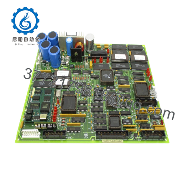
| Components | >55 ICs, FPGA, EPROM, oscillator circuits |
| Connectors | 5 vertical cable connectors + headers |
| Jumper Configuration | >20 configurable jumpers |
| Diagnostics | LED indicators + test points |
| Operating Temperature | 0°C to +60°C |
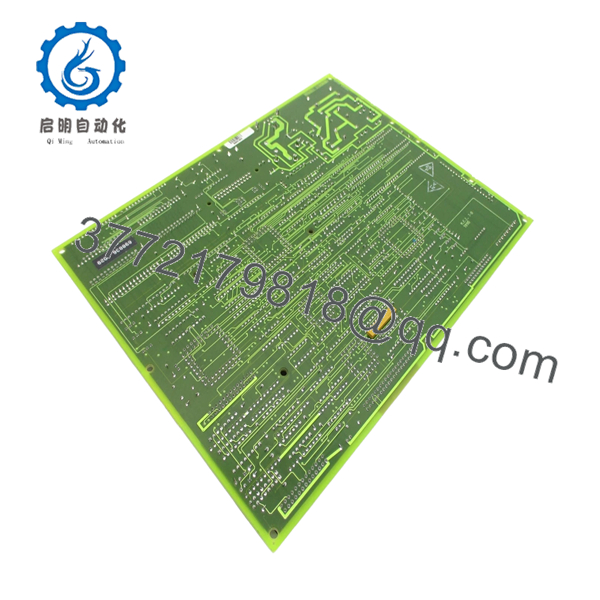
| Mounting | Rack-mounted PCB (Mark V card cage) |
4. Product Introduction
The GE DS215DMCBG1AZZ03A is a DMCB (Drive Main Control Board) used in the Mark V Speedtronic turbine control system. It handles core processing, communication, and coordination between drive subsystems, including interaction with auxiliary boards and network interfaces.
In real plant environments, this board functions as a hybrid between a controller and a communication hub. It integrates firmware, FPGA logic, and multiple processing elements to manage deterministic control tasks and system-level coordination across turbine drive assemblies.
5. Installation & Configuration Guide
Stage 1: Pre-Installation Preparation (Estimated 10–15 minutes)
- ⚠️ Safety First: Shut down turbine/drive system, apply LOTO, and wait at least 5 minutes for DC bus discharge.
- Tools Required: ESD strap, PH1 screwdriver, Fluke 115 multimeter, labeling tags, smartphone.
- Data Backup:
- Backup Mark V configuration (if applicable).
- Record board slot and network connections (ARCNET, serial).
- Photograph all connectors and jumper positions.
Stage 2: Removing the Old Module (Estimated 5–10 minutes)
- Open cabinet and locate the DMCB board.
- Disconnect ribbon cables, coax (ARCNET), and connectors.
- Release retaining screws or card guides.
- Pull the board straight out — no tilting.
- Inspect backplane connectors and coax ports.
- ⚠️ Note: Keep the old board for firmware and jumper reference.
Stage 3: Installing the New Module (Estimated 10 minutes)
- Apply ESD protection before handling.
- Verify exact model: DS215DMCBG1AZZ03A (suffix matters).
- Replicate jumper settings exactly from the original board.
- Insert evenly into the rack and secure.
- Reconnect all cables (especially ARCNET coax).
- Self-Checklist:
- Jumpers match original
- All connectors seated
- Board fully inserted
Stage 4: Power-On & Testing (Estimated 10–15 minutes)
- Pre-Power Check: Verify no shorts on supply rails.
- Power-On Steps:
- Energize the control system.
- Observe LED indicators for normal boot sequence.
- Verify communication over ARCNET / service port.
- Check system status via HMI or diagnostic interface.
- Perform dry-run validation before full operation.
- ⚠️ Troubleshooting Note:
- No comms → check ARCNET coax and node addressing.
- Boot failure → suspect firmware mismatch or jumper error.
- DS215DMCBG1AZZ03A
- DS215DMCBG1AZZ03A
6. Frequently Asked Questions (FAQ)
Q1: Can this board be hot-swapped?
No. Mark V boards are not designed for hot insertion. You risk backplane damage and system instability. Always power down.
Q2: Is this model obsolete?
Yes. Mark V is a legacy GE platform. These boards are no longer manufactured and are sourced from surplus or refurbished inventory.
Q3: What does “AZZ03A” mean in the part number?
It indicates a specific hardware and firmware build. Different suffixes can change firmware compatibility and behavior.
Q4: Is this interchangeable with DS200DMCB boards?
Not directly. DS215 versions typically include updated firmware/hardware compared to DS200 variants. Always verify compatibility before substitution.
Q5: What network does this board use?
Primarily ARCNET for Mark V system communication, along with service serial interfaces.
Q6: What’s the most common failure mode?
From field experience: EPROM degradation or connector wear. After years of thermal cycling, intermittent faults start showing up.
SOP Quality Transparency
1. Inbound Inspection & Traceability
- Verified against GE part numbering and suffix structure.
- Serial and firmware labeling inspected.
- Visual inspection: no IC damage, no capacitor bulging, intact coating.
- Connector pins checked under magnification.
2. Live Functional Testing
- Tested on a GE Mark V rack with ARCNET network simulation.
- Verified boot sequence and LED diagnostics.
- Communication tested via ARCNET and serial interface.
- Auxiliary board interaction verified.
- Continuous runtime: 24-hour powered test.
- Test report available (photos/video on request).
3. Electrical Parameter Testing
- Insulation resistance >10 MΩ @ 500 V Megger.
- Ground continuity verified.
- Voltage rails checked (+5 V, ±15 V).
4. Firmware & Configuration Verification
- Firmware PROM version recorded.
- Jumper settings documented and photographed.
- Compatibility checked against Mark V system requirements.
5. Final QC & Packaging
- QC sign-off with traceable record.
- Anti-static ESD packaging.
- Foam-protected heavy-duty carton.
- QC Passed label with date.
Technical Pitfall & Survival Guide
❗ 1. Firmware / Suffix Mismatch (AZZ03A)
I’ve seen systems refuse to boot because the firmware build didn’t match the rest of the rack.
Avoidance: Always record the exact suffix before ordering.
❗ 2. Jumper Configuration Errors
This board has 20+ jumpers. One wrong setting can break communication.
Advice: Take a clear photo before removal. Don’t rely on memory.
❗ 3. ARCNET Communication Failure
Loose or improperly terminated coax will kill network comms.
Real case: System offline for hours—turned out to be a loose BNC connector.
Avoidance: Check termination and shielding.
❗ 4. Connector Wear on Legacy Systems
After years of service, connectors lose tension.
Avoidance: Inspect and reseat carefully. Replace worn connectors if needed.
❗ 5. ESD Damage During Handling
This board includes FPGA and EPROM components—very sensitive.
Avoidance: Always use a grounded wrist strap.


