
 WhatsApp: +86 16626708626
 Email:
  Phone: +86 16626708626
Description
3. Key Technical Specifications
| Parameter | Value |
|---|---|
| Manufacturer | GE General Electric |
| Model | DS215UPLAG1BZZ01A |
| Product Type | Power Supply / LAN Interface Board |
| Functional Acronym | UPLA |
| Series | EX2000 / Mark V |
| Functional Revision 1 | B |
| Functional Revision 2 | Z |
| Artwork Revision | Z |
| Input Power | 115/230 V AC, 50/60 Hz |
| Internal Outputs | 24 V and 5 V switching supply |
| Communication | DLAN+ interface |
| Serial Interface | RS-232C |
| Memory | EEPROM firmware storage |
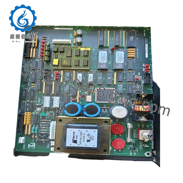
| Indicators | 1 Green Power LED, 1 Red Fault LED |
| Configuration | 28 jumpers, 2 switch banks |
| Protection | Single onboard fuse (FU1) |
| Mounting | VME rack installation |
The DS215UPLAG1BZZ01A board uses onboard EEPROM firmware architecture and acts as an updated version of the earlier DS200UPLAG1A platform.
4. Product Introduction
GE DS215UPLAG1BZZ01A is a Power Supply and LAN Interface Board used within GE EX2000 excitation and Mark V turbine control environments. The board manages regulated power distribution, firmware functions, and communication services used by excitation control assemblies.
In field deployments of excitation systems, UPLA boards frequently remain in operation long after OEM production ends. Engineers typically keep spare units available because excitation faults can shut down a turbine immediately, and replacing a board is considerably faster than redesigning an excitation architecture.
5. Installation & Configuration Guide
Stage 1: Pre-Installation Preparation
Estimated Time: 10 minutes
⚠️ Safety First: Notify operations of planned downtime. Verify safe machine state. Apply lockout/tagout procedures. Wait at least 5 minutes for discharge of stored energy.
Tools Required
- ESD wrist strap
- PH1 screwdriver
- Fluke 115 multimeter
- Wire labels
- Smartphone for documentation photos
Data Backup
- Export excitation configuration files.
- Record firmware revision details.
- Photograph jumper positions and switch bank settings.
- Document all cable routing.
- Record slot location.
Stage 2: Removing the Old Module
Estimated Time: 5 minutes
- Remove cabinet access cover.
- Label all connected cables.
- Disconnect communication and power connections.
- Release VME rack retention hardware.
- Pull board straight outward.
- Inspect edge connectors and rack pins.
⚠️ Keep the original board nearby until startup completes successfully.
I’ve watched technicians remove boards and forget switch settings. Three hours later everyone starts guessing.
Stage 3: Installing the New Module
Estimated Time: 10 minutes
- Attach grounded ESD protection.
- Verify DS215UPLAG1BZZ01A suffix matches exactly.
- Configuration Clone (Crucial): Replicate all jumper and switch bank settings.
- Confirm DLAN communication settings.
- Insert board evenly into rack guides.
- Lock retention hardware.
- Reconnect cables.
Self-Checklist:
[ ] Jumpers match
[ ] Switch banks match
[ ] Connectors secure
[ ] Lock tabs seated
❗This is the most common rookie mistake, but it happens constantly. Take a picture before you pull it. I can’t stress this enough.

- DS215UPLAG1BZZ01A
Stage 4: Power-On & Testing
Estimated Time: 5 minutes
Pre-Power Check
Use a Fluke 115 meter and verify no short exists on supply rails.
Power-Up Steps
- Energize rack power only.
- Verify Green LED illumination.
- Observe Red fault LED status.
- Verify DLAN communication.
- Connect maintenance software.
- Confirm firmware identification.
The board includes one green power LED and one red error indicator. The reset pushbutton can restart processing without removing power.
⚠️ Troubleshooting Note: Solid Red LED after startup frequently points to firmware revision mismatch or power supply issues.
Veteran Survival Guide — Technical Pitfalls
❗ Firmware Revision Mismatch
I’ve seen technicians install newer firmware revisions and spend two days troubleshooting communication timeouts. Record firmware revisions before removing the old board.
❗ DIP Switch / Jumper Misconfiguration
This board has 28 jumpers and two switch banks.
That is not a typo.
Miss one jumper and your troubleshooting shift suddenly gets much longer.
Take photos.
❗ Terminal and Connector Assumptions
Connector locations may look identical between DS200 and DS215 revisions.
Do not assume pin compatibility.
Check drawings every time.
❗ Power Consumption Oversight
Excitation systems can quietly push supply margins beyond limits. Leave at least a 20% power reserve.
❗ ESD Damage
I once watched an engineer replace a board in dry winter conditions without grounding protection. Powered it up and immediately smelled burned electronics.
That board became scrap in less than ten seconds.
Keep these checks in mind and you’ll save yourself 90% of typical rework time.
SOP Quality Transparency
1. Inbound Inspection & Traceability
- Verify OEM documentation and procurement records
- Check serial numbers and anti-counterfeit identifiers
- Inspect PCB surfaces for scratches, corrosion, rework marks, or UV discoloration
- Verify accessories and included documentation
2. Live Functional Testing
Testing performed on a genuine GE EX2000 / Mark V rack environment where available.
Procedure:
- Power-on self-test
- LED verification
- Communication handshake testing
- DLAN interface checks
- Reset testing
- Continuous runtime exceeding 24 hours
- Thermal monitoring and test report generation
Photos and startup videos available upon request.
3. Electrical Parameter Testing
- 500 V Megger insulation resistance test (>10 MΩ)
- Ground continuity verification
- Voltage measurement using Fluke 115
- Hipot testing when applicable
4. Firmware & Configuration Verification
- Read firmware version
- Record switch and jumper settings
- Photograph all hardware configuration positions
5. Final QC & Packaging
- QC inspector sign-off
- Anti-static ESD packaging
- Bubble-wrap protection
- Heavy-duty corrugated carton
- QC-passed inspection label with date
Verified fully functional under load testing.
6. Frequently Asked Questions (FAQ)
Q1: Can I hot-swap this module?
No.
Do not hot-swap this board.
VME-based Mark V and EX2000 systems were not designed for live board insertion. Pulling hardware under power can damage backplane circuitry.
Q2: Is DS215UPLAG1BZZ01A obsolete?
Yes.
This board belongs to GE’s legacy EX2000 and Mark V control environment. Current inventory typically comes from surplus stock or specialized industrial suppliers.
Q3: Is DS215UPLAG1BZZ01A a direct replacement for DS200UPLAG1A?
Generally yes, but verify firmware and configuration details first.
The DS215 version functions as an updated implementation with EEPROM-based firmware handling. Never assume drop-in compatibility without documentation review.
Q4: Will I lose programming if I replace this board?
Usually no.
The board contains firmware functionality but does not operate as the primary turbine application processor. Still back up everything. Experience teaches that assumptions become expensive during outages.
Q5: Why is the Red LED illuminated after installation?
Start with the onboard fuse FU1 and configuration settings.
I’ve watched maintenance teams replace perfectly good hardware only to discover a blown fuse or jumper issue. FU1 is one of the first checkpoints during troubleshooting.
Q6: Why is pricing lower than original OEM pricing?
Most available inventory comes from project cancellations, surplus procurement channels, and decommissioned facilities rather than active OEM manufacturing.
Q7: Are startup test reports available?
Yes.
Request communication screenshots, startup photos, thermal test logs, and load verification reports before shipment. That documentation usually prevents avoidable startup surprises.


