
 WhatsApp: +86 16626708626
 Email:
  Phone: +86 16626708626
Description
3. Key Technical Specifications
| Parameter | Value |
|---|---|
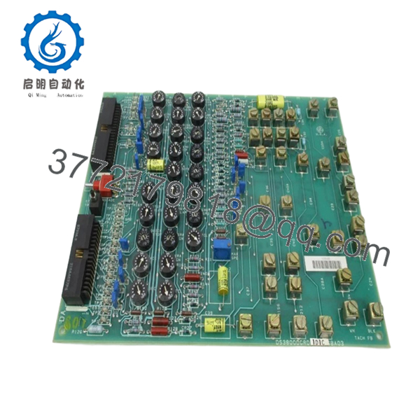
| Manufacturer | General Electric |
| Model Number | DS3800DGRD1D1C |
| Product Series | Speedtronic Mark IV DS3800 |
| Board Type | Auxiliary Drive Control Board |
| Application | Gas Turbine Control Systems |
| Connector Ports | 34-pin and 40-pin male connectors |
| Jumper Configuration | 48 configurable jumper pins |
| Test Points | 25 onboard diagnostic test points |
| Switches | SW1 black switch, SW2 red switch |
| Component Population | Capacitors, resistors, diodes, jumper arrays |
| Mounting Style | Rack-mounted industrial PCB |
| PCB Coating | Standard industrial conformal coating |
| ESD Handling Requirement | Mandatory grounded handling procedures |
| Typical Installation | GE Mark IV turbine control cabinets |
| Approximate Weight | 0.4–0.6 kg |
| Operating Environment | Air-conditioned industrial control room preferred |
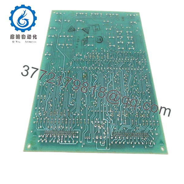
The DS3800DGRD1D1C is used in GE Speedtronic Mark IV gas turbine control systems as an auxiliary drive interface and configurable control board. Verify cabinet compatibility and revision matching before installation.
4. Product Introduction
The GE DS3800DGRD1D1C is an Auxiliary Drive Control Board designed for GE Speedtronic Mark IV turbine control systems. It handles auxiliary interface functions, configurable control logic paths, and diagnostic monitoring inside legacy gas turbine cabinets.
In real-world plant maintenance environments, this board is still commonly retained because many Mark IV systems continue operating in peaking plants, compressor stations, and industrial turbine applications. Engineers typically replace the board directly rather than performing a full turbine controls migration during an outage window.
- DS3800DGRD1D1C

- DS3800DGRD1D1C
5. Installation & Configuration Guide
Stage 1: Pre-Installation Preparation (Estimated Time: 10–15 Minutes)
⚠️ Safety First
- Notify operations before shutdown.
- Verify turbine system safe state.
- Apply lock out/tag out procedures.
- Wait at least 5 minutes for capacitor discharge.
- Confirm zero voltage with a Fluke 115 multimeter.
Mark IV cabinets may retain residual energy longer than expected, especially in older power supply assemblies.
Tools Required
- Grounded ESD wrist strap
- PH1 screwdriver
- Fluke 115 multimeter
- Wire labels
- Smartphone for reference photos
- ESD-safe work surface
- Flashlight for cabinet inspection
Data Backup
- Export turbine configuration data if accessible.
- Record cabinet slot position.
- Photograph:
- Jumper settings
- Connector orientation
- Ribbon cable routing
- Ground straps
- Label every disconnected cable.
⚠️ I’ve seen engineers skip the photo step because “it’s only two connectors.” Four hours later they’re tracing pinouts manually during startup troubleshooting.
Stage 2: Removing the Old Module (Estimated Time: 5–10 Minutes)
- Remove the cabinet front cover.
- Label and disconnect all ribbon and signal connectors.
- Do not force connector removal.
- Remove mounting hardware carefully.
- Pull the board straight outward to avoid damaging edge connectors.
- Inspect:
- Connector oxidation
- Bent pins
- Heat damage
- Dust buildup
- Cracked solder joints
⚠️ Important: Keep the original board until the replacement passes operational testing.
I’ve watched maintenance crews discard the old board too early, only to discover the replacement revision had different jumper defaults.
Stage 3: Installing the New Module (Estimated Time: 10 Minutes)
- Wear the grounded ESD strap before touching the board.
- Verify exact model number:
- DS3800DGRD1D1C
- Compare board revision markings carefully.
Configuration Clone (Crucial)
Replicate:
- J1–J48 jumper positions
- Switch settings
- Connector orientation
- Shield grounding configuration
⚠️ This is the most common startup issue with Mark IV hardware. One misplaced jumper can create intermittent turbine faults that only appear under load.
- Insert the board evenly into the rack guides.
- Tighten mounting screws evenly.
- Reconnect all cables carefully.
Self-Checklist
- Model numbers match
- Jumper settings duplicated
- Ribbon cables fully seated
- Grounding verified
- Mounting secured
- No loose hardware inside cabinet
Stage 4: Power-On & Testing (Estimated Time: 15–20 Minutes)
Pre-Power Check
- Verify no short on the 24 V control rail.
- Confirm cabinet grounding continuity.
- Inspect all connectors for proper seating.
Power-On Sequence
- Energize the control rack first.
- Observe startup indicators.
- Verify communication with the Mark IV controller.
- Monitor for watchdog or initialization alarms.
- Connect engineering workstation if available.
- Perform dry-run signal testing before enabling field devices.
Functional Verification
Check:
- Stable communication
- Proper auxiliary interface response
- No intermittent alarms
- Stable diagnostic test point readings
Use onboard test points TP1–TP25 for troubleshooting and recalibration if required.
⚠️ Troubleshooting Note
If startup faults appear immediately after installation:
- First suspect jumper mismatch.
- Second verify connector orientation.
- Third inspect firmware and controller revision compatibility.
I once saw a technician install a visually identical DS3800 board with different jumper defaults during a midnight outage. The turbine stayed in startup inhibit for nearly six hours before anyone noticed the configuration mismatch.
Technical Pitfall & Survival Guide
❗ Firmware and Revision Compatibility
Mark IV hardware revisions are not always interchangeable.
Avoidance:
Document all suffixes and board revision labels before ordering replacements.
I’ve seen communication faults caused by minor hardware timing differences between revisions.
❗ Jumper Configuration Errors
This board contains 48 jumper points for configuration flexibility.
Avoidance:
Photograph every jumper before removal. Replicate settings exactly.
Do not trust factory defaults.
❗ Connector Misalignment
The 34-pin and 40-pin connectors can be damaged easily during insertion.
Avoidance:
Insert the board straight and evenly.
Bent connector pins create intermittent faults that are miserable to troubleshoot during turbine startup.
❗ Power Supply Loading
Older Mark IV cabinets often run near PSU limits.
Avoidance:
Verify total cabinet current draw and maintain a 20% safety margin.
❗ Electrostatic Discharge (ESD)
These legacy GE boards are highly sensitive to static damage.
Avoidance:
Use grounded ESD handling procedures and anti-static packaging.
I once watched an engineer pull a spare board from standard bubble wrap instead of an ESD bag. Powered it up and immediately lost two communication channels. Expensive lesson.
Keep these checks in mind and you’ll save yourself 90% of typical rework time.
6. Frequently Asked Questions (FAQ)
Q1: Can I hot-swap the DS3800DGRD1D1C?
No.
This board was not designed for live insertion. Hot-swapping can damage the backplane, corrupt controller communications, or trip the turbine control system.
Always power down the cabinet first.
Q2: Is the DS3800DGRD1D1C obsolete?
Yes.
The GE Mark IV platform is considered legacy equipment. Most available inventory today comes from:
- New surplus stock
- Plant spare inventories
- Refurbished tested units
Factory-sealed inventory exists in limited quantities globally.
Q3: What are the onboard test points used for?
The board includes 25 diagnostic test points labeled TP1 through TP25.
These are used for:
- Signal tracing
- Calibration
- Voltage verification
- Troubleshooting communication faults
They are extremely useful during field diagnostics.
Q4: Will replacing this board erase turbine logic?
Usually no.
The DS3800DGRD1D1C itself does not normally contain the primary turbine application logic. That logic generally resides in the main Mark IV processors.
However, jumper settings and configuration states still matter greatly.
Q5: Why are some units much cheaper than others?
Usually because of:
- Unknown test status
- Missing traceability
- Cosmetic damage
- Refurbished inventory sold unclearly
Always request:
- Board photos
- Test reports
- Serial labels
- Packaging photos
- Runtime verification details
A serious supplier should provide all of them.
Q6: What should I verify before ordering?
At minimum verify:
- Exact model number
- Revision suffix
- Jumper configuration
- Connector compatibility
- Cabinet slot assignment
- Existing system revision
Even visually similar DS3800 boards may not be electrically interchangeable.
Q7: What quality testing should a supplier perform?
Minimum acceptable QC should include:
- Visual inspection under magnification
- Connector integrity inspection
- Insulation resistance testing (>10 MΩ preferred)
- Controlled power-up verification
- Diagnostic signal testing
- 24-hour runtime testing
- ESD-safe packaging and sealing
Good suppliers will also provide:
- QC reports
- Test videos
- High-resolution photos
- Packaging verification before shipment
A board tested on an actual GE Mark IV rack means far more than a simple “power-on tested” sticker.


