
 WhatsApp: +86 16626708626
 Email:
  Phone: +86 16626708626
Description
3. Key Technical Specifications
| Parameter | Value |
|---|---|
| Manufacturer | GE General Electric |
| Model Number | DS3800HMPK1F1F |
| Product Type | Regulator Control Board |
| System Family | GE Mark IV Speedtronic |
| Platform | DS3800 Series |
| Application | Turbine control and regulation |
| Board Function | Voltage and process regulation |
| Installation Type | Rack-mounted PCB |
| Operating Temperature | 0 °C to +60 °C |
| Storage Temperature | −20 °C to +85 °C |
| Humidity Rating | 5–95%, non-condensing |
| Board Revision | F1F1F |
| Approximate Weight | 0.45–0.9 kg |
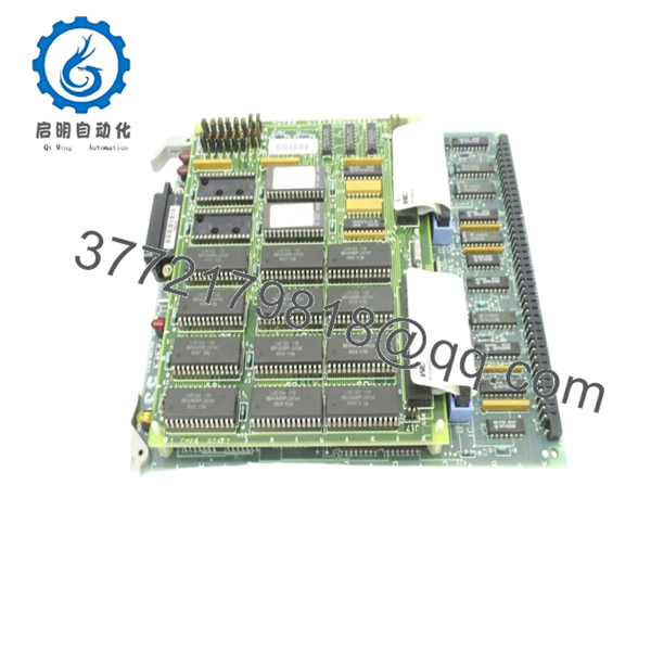
The DS3800HMPK1F1F is identified as a GE Mark IV Regulator Control Board designed for control and regulation functions inside Speedtronic systems. Available inventory today typically comes from surplus channels because OEM production ended years ago.
4. Product Introduction
GE DS3800HMPK1F1F is a Mark IV Regulator Control Board used within GE Speedtronic turbine control systems. The board performs control and regulation functions associated with turbine operating stability and internal process management.
In field deployments of older Mark IV systems, boards like DS3800HMPK1F1F become critical maintenance inventory because replacing an entire turbine control platform during a forced outage usually creates more downtime than maintaining the installed architecture. Most inventory now enters the market as New Surplus or tested refurbished stock.

- DS3800HMPK1F1F
5. Installation & Configuration Guide
Stage 1: Pre-Installation Preparation
Estimated Time: 10 minutes
⚠️ Safety First: Notify operations personnel. Confirm turbine process safe state. Apply lockout/tagout procedures and wait at least 5 minutes for stored energy discharge.
Tools Required
- ESD wrist strap
- PH1 screwdriver
- Fluke 115 multimeter
- Wire labels
- Smartphone for photos
- Flashlight
Data Backup
- Export available system diagnostics
- Record alarm history
- Photograph all cable positions
- Capture jumper and hardware settings
- Photograph revision labels
❗I’ve watched experienced technicians skip photos because “it’s only one board.” Thirty minutes later they’re tracing connectors one pin at a time.
Stage 2: Removing the Old Module
Estimated Time: 5–8 minutes
- Remove enclosure covers.
- Label all connections before removal.
- Disconnect cables carefully.
- Release retention hardware.
- Pull the PCB straight outward.
Inspect:
- Backplane contacts
- Edge connector wear
- Dust accumulation
- Bent pins
⚠️ Keep the original board beside the rack during startup.
Old boards become valuable references when troubleshooting begins.
Stage 3: Installing the New Module
Estimated Time: 5 minutes
- Wear ESD protection before touching the PCB.
- Verify exact part number: DS3800HMPK1F1F
- Configuration Clone (Crucial): Replicate all jumpers and settings exactly.
- Insert board evenly using guide rails.
- Confirm retention hardware locks fully.
- Reconnect field wiring.
Self-Checklist
- Jumpers match original
- Wiring secured
- Board seated completely
- Retention tabs engaged
❗This is the most common rookie mistake, but it happens constantly. Take a picture before you pull it. I can’t stress this enough.
Stage 4: Power-On & Testing
Estimated Time: 10 minutes
Pre-Power Check
Use a Fluke 115 and verify no short condition exists across power rails.
Power Sequence
- Energize rack only
- Observe startup indicators
- Verify communication status
- Connect engineering workstation if available
- Perform dry-run I/O simulation
⚠️ Troubleshooting Note: If communication or regulation faults appear immediately after startup, inspect hardware revisions and jumper settings before replacing additional hardware.
Technical Pitfall & Survival Guide
❗Firmware Revision Mismatch
Mark IV systems accumulated hardware changes over decades.
I saw a replacement project lose two shifts because a newer board revision behaved differently enough to trigger communication timeout alarms.
Avoidance:
- Record revision labels before removal
- Request matching revision levels
- Photograph hardware markings
❗DIP Switch / Jumper Misconfiguration
Factory settings rarely match installed systems.
Take a photo before removing anything.
Then take another one.
❗Terminal Block / Wiring Assumptions
Even visually similar DS3800 boards can have different assignments.
Do not wire from memory.
Always verify drawings.
❗Power Draw Specifications
Calculate rack loading and maintain a 20% reserve.
An overloaded supply often creates unstable faults before complete failure.
❗Electrostatic Discharge
I once watched an engineer unpack a board during winter without an ESD strap.
Powered once.
Never powered again.
That lesson cost several thousand dollars.
Keep these checks in mind and you’ll save yourself 90% of typical rework time.
SOP Quality Transparency
1. Inbound Inspection & Traceability
- Verify OEM shipping documentation
- Review serial labels and anti-counterfeit markings
- Inspect for scratches, corrosion, UV discoloration, or repair evidence
- Audit included documentation and accessories
2. Live Functional Testing
Test Environment
- Genuine GE Mark IV rack
- Simulated turbine control environment
Procedure
- Power-on self-test
- LED status verification
- Communication handshake validation
- I/O signal simulation
- Continuous operation >24 hr with thermal monitoring
- Formal test report generation
Test videos and photos are available upon request.
3. Electrical Parameter Testing
- 500 V Megger insulation test (>10 MΩ)
- Ground continuity verification
- Hipot testing where applicable
4. Firmware & Configuration Verification
- Record hardware revision
- Document jumper positions
- Photograph labels and settings
5. Final QC & Packaging
- QC inspector signoff
- Anti-static ESD packaging
- Bubble protection
- Heavy-duty corrugated packaging
- QC passed date labeling
Verified fully functional under load testing.
6. Frequently Asked Questions (FAQ)
Q1. Can I hot-swap DS3800HMPK1F1F?
No.
Do not attempt live insertion. Mark IV systems were not designed for hot-swapping. Pulling the board under power risks backplane damage and secondary faults.
Power down first.
Q2. Is this model obsolete?
Yes.
Mark IV hardware has been out of OEM production for years. Current inventory primarily comes through surplus and tested secondary channels.
Q3. Is New Surplus inventory actually unused?
Sometimes yes.
Sometimes inventory sat in storage for twenty years.
Ask for:
- Label photos
- Packaging photos
- Test reports
- Manufacturing codes
Do not assume.
Q4. Will replacing this board erase application logic?
Typically no.
The DS3800HMPK1F1F acts as a regulator control board rather than the main processor. Still verify architecture details before shutdown.
Q5. Why are prices so inconsistent?
Obsolete turbine hardware pricing follows availability rather than original list price.
Current listings vary widely, with stock condition and warranty terms affecting pricing. One listing showed approximately USD 5,400 tested inventory while another listed New Surplus stock above USD 6,100.
Q6. Is refurbished inventory acceptable for critical systems?
Depends on outage risk.
For scheduled maintenance, tested refurbished hardware often makes sense. For emergency spares on critical turbine systems, many maintenance teams still request New Surplus inventory.
Q7. What should I inspect first if faults continue after replacement?
Start with:
- Revision matching
- Jumper configuration
- Edge connector condition
- Backplane contact integrity
I’ve seen oxidized connectors create faults that looked exactly like failed boards.


