
 WhatsApp: +86 16626708626
 Email:
  Phone: +86 16626708626
Description
3. Key Technical Specifications
| Parameter | Value |
|---|---|
| Manufacturer | General Electric (GE) |
| Model Number | DS3800HMPK1G1G |
| Product Type | Microprocessor Control Board |
| Series | GE Mark IV / Drive Control Platform |
| Primary Function | System logic and control processing |
| Processor Type | Industrial microprocessor architecture |
| Memory Type | EPROM modules |
| Diagnostic LEDs | Multiple onboard status LEDs |
| Connector Types | 34-pin and dual 50-pin connectors |
| Mounting Method | Rack-mounted PCB |
| PCB Coating | Industrial conformal coating |
| Communication Interface | Internal drive/control bus |
| Power Source | Backplane-powered |
| Application | Turbine and industrial drive systems |
| Cooling Requirement | Forced-air cabinet cooling recommended |
| Operating Environment | Industrial control cabinet |
| Approximate Weight | 4.3 kg |
| Country of Origin | USA |
| Condition Options | New Original, New Surplus, Refurbished (tested) |
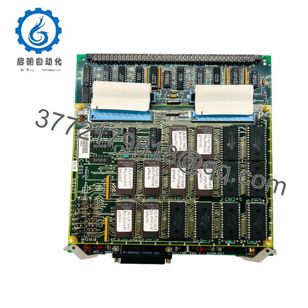
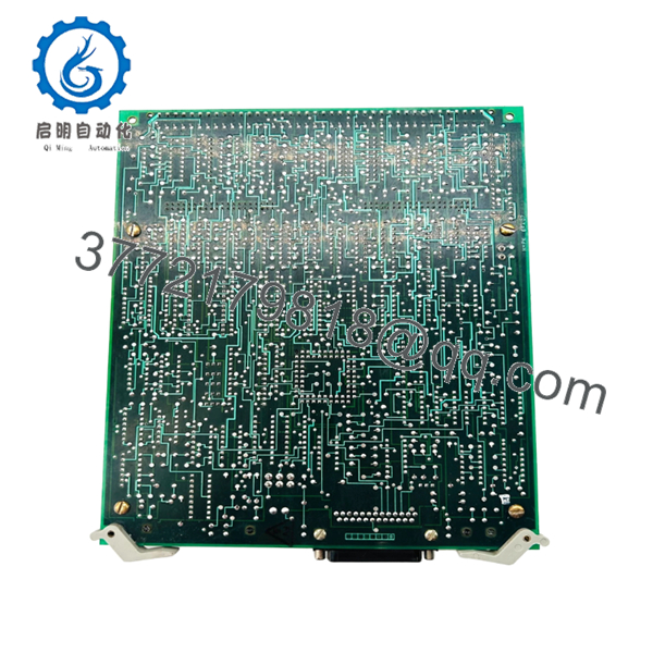
The DS3800HMPK1G1G is a GE microprocessor-based control board used in legacy Mark IV and industrial drive control systems. Similar HMPK-series boards include onboard EPROM memory, diagnostic LEDs, and multi-pin interface connectors for communication with associated control hardware.
4. Product Introduction
The GE DS3800HMPK1G1G is a microprocessor control board used in GE legacy turbine and industrial drive systems. It handles internal logic execution, system coordination, and communication with connected control assemblies through rack-mounted interface connections.
In real plant environments, these older GE processor boards are usually maintained because replacing the entire cabinet architecture would require major downtime, field rewiring, and software migration work. Engineers typically prioritize matching revision levels carefully since older GE systems can become unstable when processor and interface boards are mixed across incompatible revisions.
5. Installation & Configuration Guide
Stage 1: Pre-Installation Preparation (Estimated Time: 10 Minutes)
⚠️ Safety First
- Notify operations before shutting down the control cabinet.
- Place the driven equipment into a verified safe state.
- Apply lock out/tag out procedures to all incoming AC and DC sources.
- Wait at least 5 minutes for capacitor discharge.
- Verify zero voltage using a Fluke 115 or equivalent multimeter.
Tools Required
- ESD wrist strap
- PH1 screwdriver
- Multimeter
- Wire labels
- Smartphone for cabinet photos
- Flashlight
Data Backup
- Export existing control configuration if supported.
- Photograph:
- Ribbon cable routing
- Connector placement
- Jumper settings
- Cabinet grounding
- Record all installed board revision numbers.
❗ Legacy GE cabinets often contain undocumented field modifications from decades of outages and retrofits. Never assume the cabinet still matches the original prints exactly.
Stage 2: Removing the Old Module (Estimated Time: 5 Minutes)
- Remove the cabinet access panel.
- Label every ribbon cable and connector individually.
- Disconnect connectors carefully by gripping the connector body.
⚠️ Important
Do not pull directly on ribbon cables. Older GE ribbon assemblies become brittle with heat cycling and age. I’ve seen conductors separate internally even though the insulation looked fine externally.
- Remove mounting hardware evenly.
- Pull the board straight outward without twisting.
Inspect the Cabinet Area
Check for:
- Dust buildup
- Loose hardware
- Burn marks
- Corrosion
- Capacitor leakage
- Bent connector pins
⚠️ Keep the old board
Retain the original module until the replacement operates correctly under load.
Stage 3: Installing the New Module (Estimated Time: 10 Minutes)
- Attach your grounded ESD strap before handling the board.
- Verify:
- Exact model number
- G1G suffix
- Connector layout
- Compatible rack architecture
❗ Configuration Clone (Critical)
Replicate all jumper and connector configurations exactly from the original board.
This is where replacement jobs usually go sideways.
I’ve seen maintenance teams install the correct GE board but reverse one ribbon connector orientation. The cabinet powered up, diagnostics looked normal initially, then communication faults started appearing intermittently once the drive entered operation.
Take clear photos before removal.
- Install the DS3800HMPK1G1G evenly into the rack guides.
- Tighten mounting hardware carefully.
- Reconnect all ribbon and interface connectors fully.
Self-Checklist
- Connectors aligned correctly
- Jumpers duplicated
- Hardware tightened
- Grounding verified
- No loose objects inside cabinet
Stage 4: Power-On & Testing (Estimated Time: 15 Minutes)
Pre-Power Check
- Verify no shorts exist on incoming supply rails.
- Confirm cabinet grounding continuity.
- Inspect connector seating one final time.
Power-On Procedure
- Energize the control rack only.
- Observe onboard diagnostic LEDs.
- Verify normal startup sequencing.
- Check communication with associated control boards.
- Confirm no processor or watchdog faults appear.
- Perform dry-run operational checks before returning the process to service.
⚠️ Firmware and EPROM Revision Mismatch
Older GE systems can become unstable from revision mismatches that look minor on paper.
I’ve personally seen cabinets boot normally after a processor board swap, then fail unpredictably because the EPROM revision differed slightly from the associated interface boards.
Before replacement:
- Document EPROM labels
- Record firmware revisions
- Match replacement revisions carefully
⚠️ Connector Misalignment
This is one of the most common field mistakes.
Several connectors on older GE boards look nearly identical. One offset connector row can prevent startup entirely or damage interface circuitry.
Never reconnect cables from memory.
⚠️ Power Supply Margin
Do not assume aging cabinet power supplies still deliver rated output.
I’ve measured older GE supplies drifting badly once cabinet temperatures rise during summer operation. Leave at least 20% power margin whenever possible.
⚠️ ESD Damage
Always use grounding protection.
I once watched a contractor unpack a spare GE processor board directly onto cardboard during winter maintenance. Static discharge damaged the board before installation even started. The cabinet faulted immediately during boot.
Keep these checks in mind and you’ll save yourself 90% of typical rework time.

- DS3800HMPK1G1G
- DS3800HMPK1G1G
6. Frequently Asked Questions (FAQ)
Q1: Can the DS3800HMPK1G1G be hot-swapped?
No.
This board is not designed for live insertion or removal. Pulling the board under power can damage the backplane, corrupt communications, or fault the entire control cabinet.
Always isolate power completely before replacement.
Q2: Is the DS3800HMPK1G1G obsolete?
Yes.
This board belongs to an older GE control generation and is considered legacy hardware. Most available inventory now comes from surplus stock, decommissioned systems, or specialized industrial automation suppliers.
Stock availability can change quickly during outage seasons.
Q3: What does this board actually do?
The DS3800HMPK1G1G functions as a microprocessor control board.
It processes internal logic, coordinates communication between connected assemblies, and supports system-level control functions inside GE drive and turbine architectures. Similar HMPK-series boards include onboard EPROM memory and diagnostic LEDs.
Q4: Are all DS3800HMPK revisions interchangeable?
Not necessarily.
Older GE systems are sensitive to:
- Revision suffixes
- EPROM versions
- Connector assignments
- Cabinet architecture differences
The board may physically fit while still causing communication or timing faults.
Always verify compatibility before installation.
Q5: What is the most common installation mistake?
Ribbon cable misalignment.
Honestly, this causes more startup headaches than actual board failure. Many connectors look nearly identical, especially under outage pressure inside crowded cabinets.
Take photos before disconnecting anything.
Q6: Why do these older GE boards fail?
Typical causes include:
- Heat stress
- Aging capacitors
- Dust contamination
- Vibration fatigue
- Power supply instability
- ESD damage during handling
I’ve opened older GE cabinets where the boards looked clean from the front but had conductive dust packed underneath for years.
Q7: What testing should be completed before shipment?
A proper QC workflow should include:
- OEM traceability verification
- Serial number inspection
- Visual inspection for corrosion or rework marks
- EPROM verification
- Power-on testing using a compatible GE rack
- Diagnostic LED verification
- Connector integrity testing
- Insulation resistance testing using a 500 V Megger
- Burn-in testing under load for at least 24 hours
- ESD-safe packaging and final QC sign-off
Verified fully functional under load testing. Test reports and startup videos should be available upon request.



