
 WhatsApp: +86 16626708626
 Email:
  Phone: +86 16626708626
Description
3. Key Technical Specifications
| Parameter | Value |
|---|---|
| Manufacturer | GE |
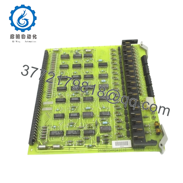
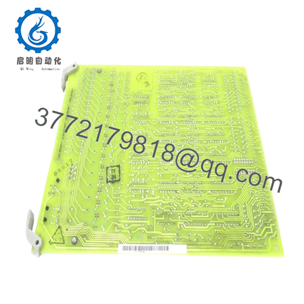
| Model | DS3800HRDA1C1C |
| Product Family | DS3800 Series |
| Platform | GE Mark IV Speedtronic |
| Board Type | Buffer Decoder Board |
| Product Category | Industrial Control PCB |
| Storage Components | EPROM / EEPROM assemblies |
| Indicators | Multiple onboard LED diagnostics |
| Mounting Method | Rack-installed PCB |
| Communication | Proprietary GE Mark IV architecture |
| Revision Dependency | High |
| Condition | New Original / New Surplus |
4. Product Introduction
The GE DS3800HRDA1C1C is a Buffer Decoder Board used within GE Mark IV Speedtronic turbine control systems. It performs signal handling and decoding functions required by the control architecture and interfaces with other system boards through backplane and connector assemblies.
In field deployments of aging turbine systems, these boards remain in service because a complete Mark IV migration often means substantial downtime and engineering effort. Replacement success depends heavily on revision matching and configuration verification rather than visual board similarity.

- DS3800HRDA1C1C
- DS3800HRDA1C1C
5. Installation & Configuration Guide
Stage 1: Pre-Installation Preparation (Estimated: 10 minutes)
⚠️ Safety First: Notify operations of downtime. Confirm machine shutdown state. Apply lockout/tagout procedures and wait 5 minutes after power removal for discharge.
Tools Required
- ESD wrist strap
- PH1 screwdriver
- Fluke 115 multimeter
- Wire labels
- Smartphone for documentation
- ESD mat
Data Backup
- Export controller configuration where possible
- Record cabinet slot locations
- Photograph DIP switch settings
- Photograph cable routing
- Record all connector labels
- Record board revision markings
Stage 2: Removing the Old Module (Estimated: 5–10 minutes)
Steps:
- Remove enclosure covers
- Label all wiring and connectors
- Disconnect harnesses carefully
- Release board retention clips
- Pull board straight outward
⚠️ Note: Keep the original board beside the cabinet until startup verification finishes.
Inspect:
- Backplane connector condition
- Bent pins
- Dust buildup
- Corrosion
- Heat damage around connectors
Stage 3: Installing the New Module (Estimated: 10 minutes)
Steps:
- Connect ESD strap before handling board
- Verify DS3800HRDA1C1C exactly matches
- Configuration Clone (Crucial)
- Match jumper positions
- Match switch settings
- Match addressing selections
- Verify all connector orientation
This is the most common rookie mistake, but it happens constantly. Take a picture before you pull it. I can’t stress this enough.
- Install board evenly
- Push until fully seated
- Secure retention hardware
- Reconnect wiring
Self-Checklist
- DIPs match
- Wiring secured
- Board fully seated
- Tabs locked
Stage 4: Power-On & Testing (Estimated: 10–15 minutes)
Pre-Power Check
Use a multimeter to verify no shorts on power rails.
Power sequence:
- Power rack only
- Observe LED behavior
- Verify startup sequence
- Connect engineering workstation
- Verify communication status
- Restore configuration if needed
- Conduct dry I/O testing
LED guideline:
- Green RUN = expected operation
- Red ERR = fault detected
⚠️ Troubleshooting Note: Solid fault indicators immediately after replacement frequently indicate board revision or firmware incompatibility.
I have seen maintenance crews replace multiple boards before discovering the issue was revision mismatch.
Technical Pitfall & Survival Guide
❗ Firmware Revision Mismatch
Issue:
Replacement boards from surplus inventories may contain different firmware generations.
Avoidance:
Record firmware labels before removal and request matching revisions.
I’ve seen systems sit idle for two days because a replacement revision changed communication behavior enough to trigger timeout alarms. Documentation solved it in ten minutes.
❗ DIP Switch / Jumper Misconfiguration
Issue:
Factory defaults rarely match site settings.
Avoidance:
Take photographs before removing hardware.
This is the most common rookie mistake. It happens constantly.
❗ Terminal Block / Wiring Differences
Issue:
Connector assignments may differ between revisions.
Warning:
Even similar GE assemblies can shift connector definitions. Always verify manuals. Do not wire from memory.
❗ Power Draw Requirements
Issue:
Legacy power supplies frequently run close to limits.
Avoidance:
Calculate total rack loading and maintain a 20% capacity margin.
Unexpected startup faults often come from overloaded supplies rather than failed boards.
❗ Electrostatic Discharge (ESD)
Issue:
Board damage before startup.
Avoidance:
Use grounded wrist straps and ESD mats.
I watched an engineer handle a board in winter conditions without protection. Powered up once and never again. Expensive lesson.
Keep these checks in mind and you’ll save yourself 90% of typical rework time.
Quality Inspection & Functional Verification SOP
1. Inbound Inspection & Traceability
- OEM packing verification
- Serial verification
- Anti-counterfeit inspection
- Visual inspection for:
- scratches
- corrosion
- solder rework marks
- UV discoloration
- Accessory audit
2. Live Functional Testing
Test platform:
- Genuine GE Mark IV rack
- Simulation environment
- Fluke 115 multimeter
Testing:
- Power-on diagnostics
- LED startup verification
- Communication handshake checks
- Signal simulation
- Continuous 24-hour load operation
- Thermal monitoring
Official test reports generated.
Test photos and videos available upon request.
3. Electrical Parameter Testing
- Insulation resistance:
- 500 V Megger
- Greater than 10 MΩ
- Ground continuity verification
- Hipot testing where applicable
4. Firmware Documentation
- Record firmware revisions
- Photograph jumper settings
- Photograph switch positions
5. Final QC & Packaging
- QC sign-off
- Anti-static ESD packaging
- Bubble protection
- Heavy-duty corrugated packaging
- QC pass labeling with date
Verified fully functional under load testing.
6. Frequently Asked Questions (FAQ)
Q1: Can I hot-swap this module?
No.
GE Mark IV hardware was not intended for casual hot replacement. Removing boards under power can damage the backplane and create difficult-to-diagnose faults.
Power down first.
Q2: Is DS3800HRDA1C1C obsolete?
Yes.
The module has been discontinued and is commonly available only through surplus or tested inventories. Availability changes frequently.
Q3: Is this genuinely new or refurbished?
Inventory generally falls into:
- New Original / New Surplus
- Refurbished and tested
Always request actual inventory photos before ordering.
Q4: What does this board actually do?
The DS3800HRDA1C1C operates as a Buffer Decoder Board within GE Mark IV architecture and participates in board-level processing and signal handling.
Q5: Will I lose control logic if I remove this board?
Usually no.
Logic often resides elsewhere in Mark IV architecture, but assumptions create downtime. Backup available configuration information before touching hardware.
Q6: Why does surplus pricing vary so much?
Supply is inconsistent.
These boards often come from plant shutdown inventories, canceled projects, or unused spare stock. Obsolete hardware pricing follows availability more than original MSRP.
Q7: Is the module tested before shipment?
Yes.
Testing includes startup verification, communication checks, insulation measurements, and load operation testing prior to QC release. Test documentation can be supplied upon request.


